Hi, I just had a few questions about setting up my initial meshes.
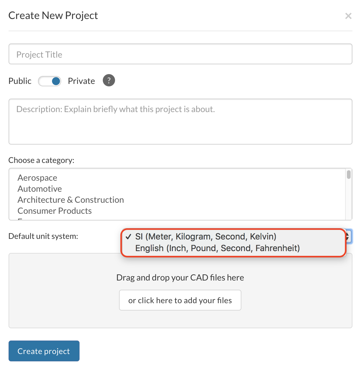
Is there a type of save file that will retain its dimensions from the CAD? I imported an STL file and my background mesh box’s dimensions were accurate according to a wind tunnel I am referencing, but the scaling was way off compared to the model.
Are imported models always centered at (0,0,0)? If not, how can I change that?
This might be sort of related to my second question, but is there a way to rotate my model to a specific degree? I want to simulate a wing at various angles of attacks.
The origin of your model is exactly the same you have defined it inside your CAD software. There are no possibilities at the moment to change that inside the workbench but what I would recommend is to work with Onshape and use the import tool. That is in my opinion the most efficient way of working when you have to make a lot of adaptions.
My advice here would also be to use Onshape and work with parametric models. Our PowerUser Darren (@1318980) has worked with some scripts in the past and I am sure he can give you more information on that one. Useful links for you in this case: Aerofoil Profile Scripts & Airfoiltools.
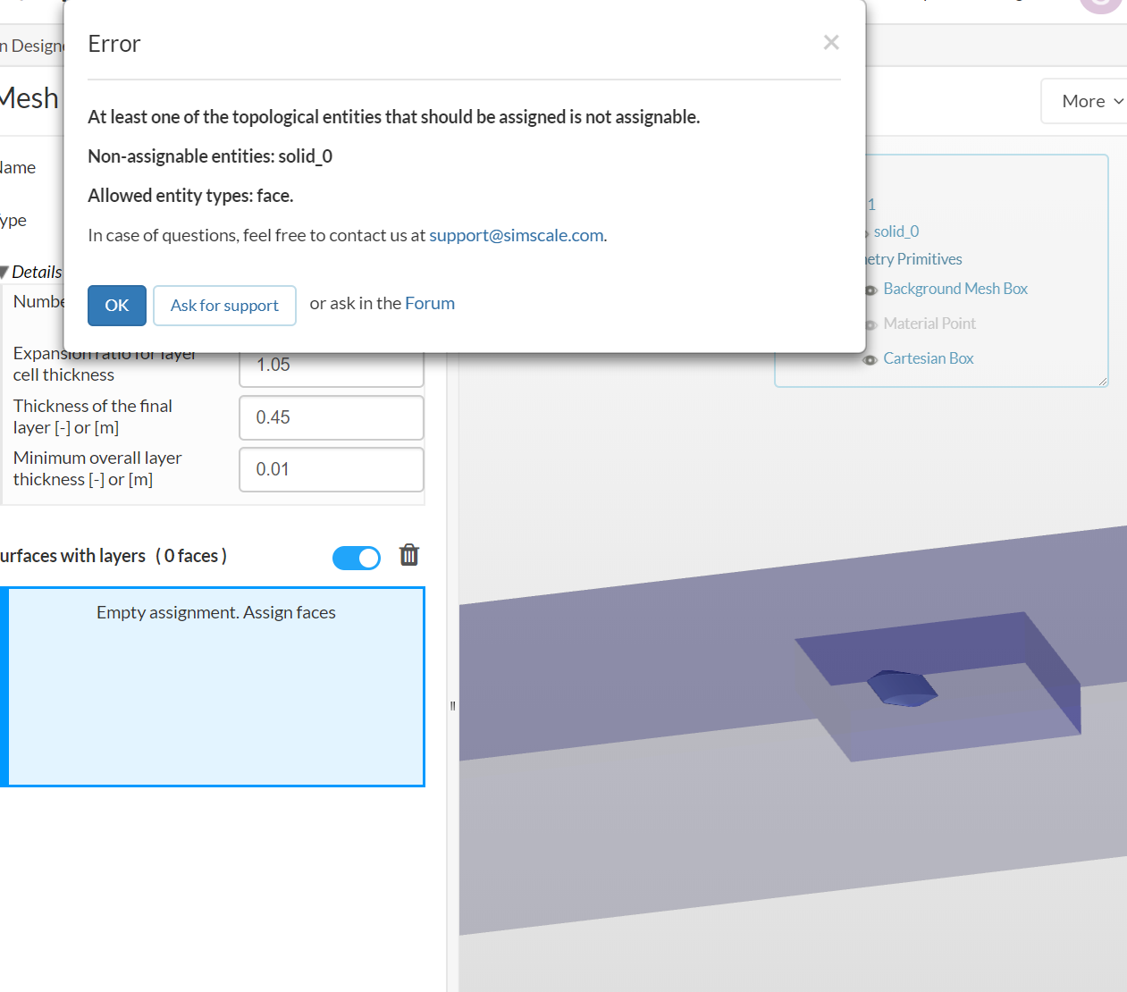
You have to make sure that you split your geometry to apply the inflate boundary layer to faces. I would suggest that you split your geometry inside a CAD software of your choice and re-upload your model.
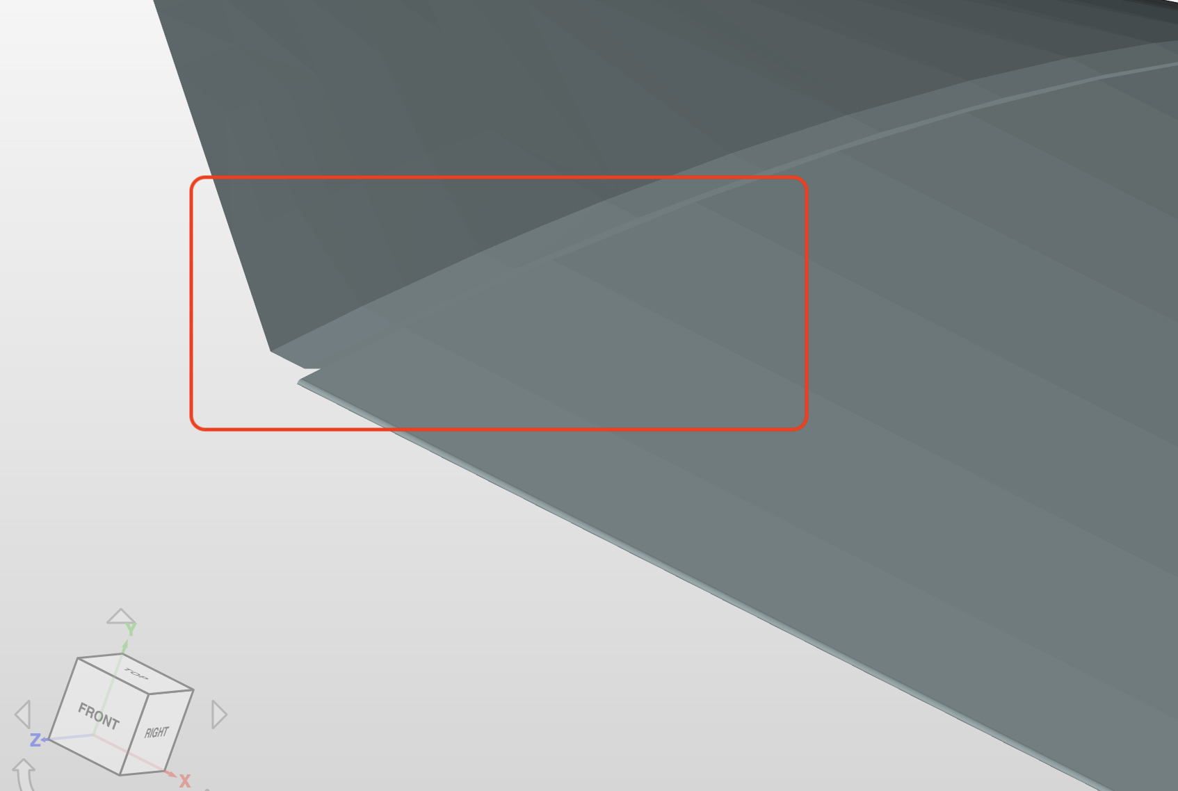
Please also make sure that your geometry is watertight because I cannot really identify if the offset you created has a closed face or is open - just to let you know
Hello @jousefm, I just uploaded it and I think I’ve figured most of it out. I really appreciate your quick responses and I’ll definitely post again if I run into any more problems. Thanks!
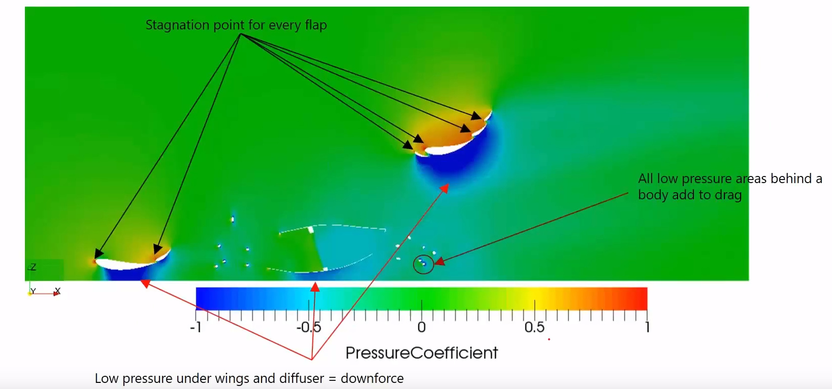
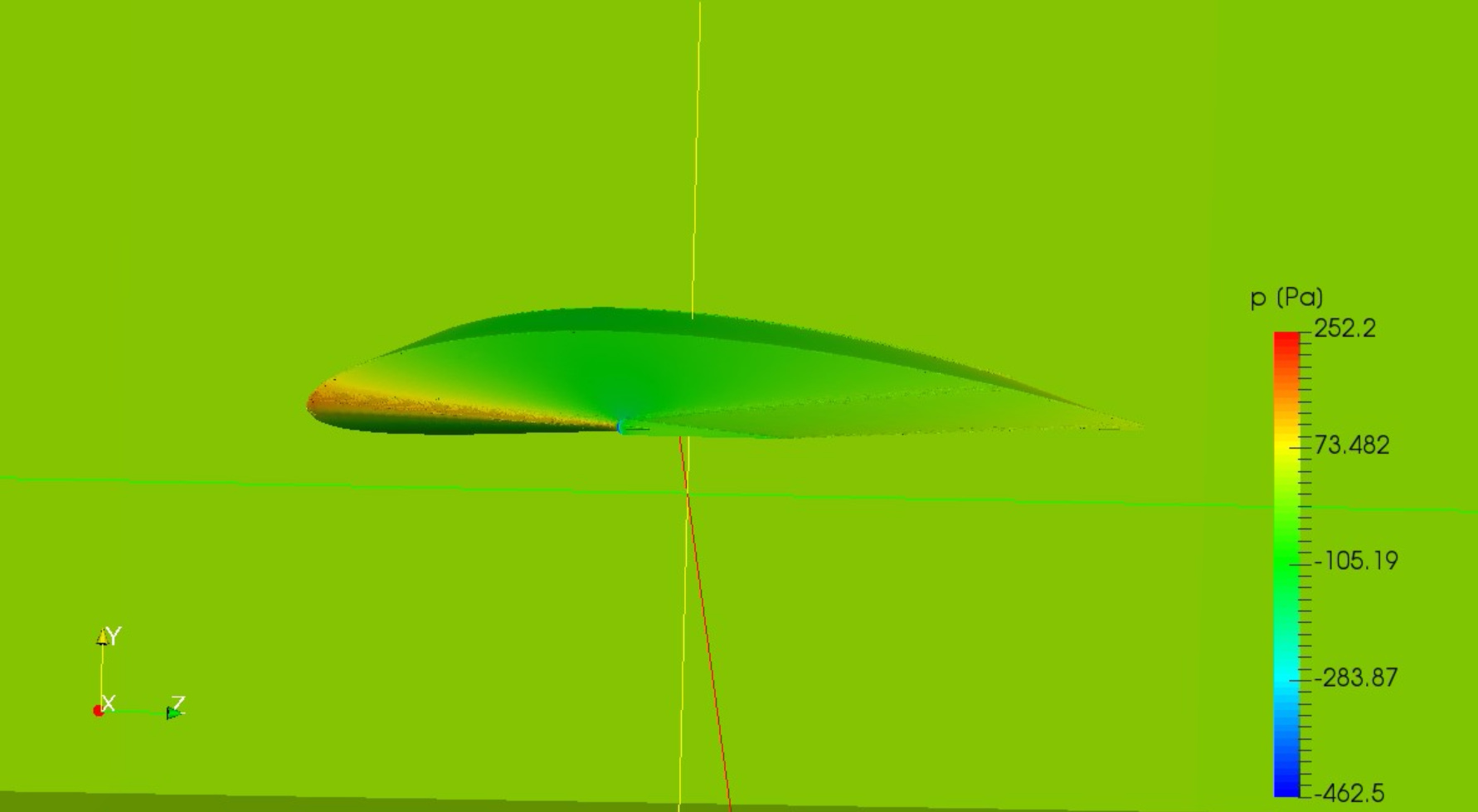
@jousefm, as promised I’m back with more questions, ha. I have finished my simulation run and I really just need some tips to obtaining results I can analyze. I would love to be able to get some visuals like this (from the Formula SAE workshop):
Where you can see the pressure gradient surrounding my model too. However, I am finding some difficulty doing this. Here is a screenshot of my simulation:
It looks like I’m only seeing pressure gradients on the surface of the model. I think part of the reason is because my cartesian box I set up to simulate the wake and air around the wing didn’t mesh for some reason?
One of the main reasons is the way you defined the boundary conditions - the inlet, outlet as well as the wall are applied on the wing and no bounding box was used at all giving you odd results. Make sure you check out some other tutorials on CFD analysis for a wing to get an understanding of how this works. I am willing to help you there but the best way to learn it is to make yourself familiar with the workbench, you can ask questions whenever you want of course.
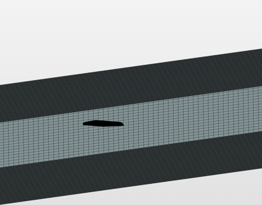
Hey @jousefm, I just got done with some exams so I can focus more attention on this. I’ve honestly tried pretty hard to get most of my simulation done myself by watching and reading tutorials, but I’m still having some trouble. My region bounding box is not meshing…
Hope your exams went well Regarding the project I have had a look at the Winglet CFD and the Wing CFD project. Both of them have a close bounding box so I am not sure what happened in your case. Maybe you accidentally clicked on the symbol. Can you check again please and get back to me?