Hello,
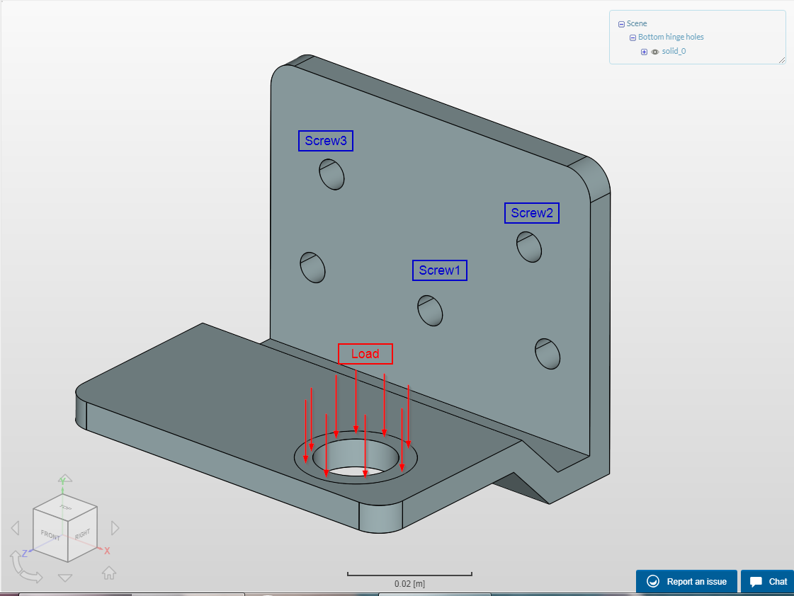
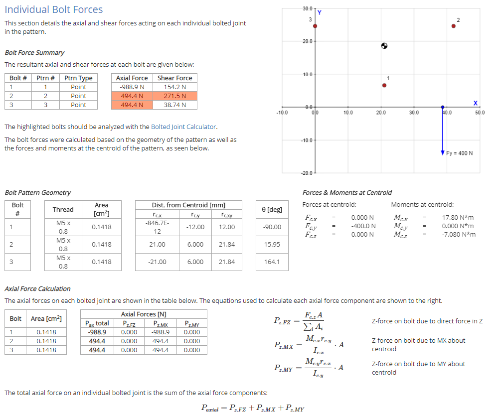
I want to analyse fastening of a bottom hinge and I determine the reaction forces in its holes. They are needed to determine the diameters of the screws.
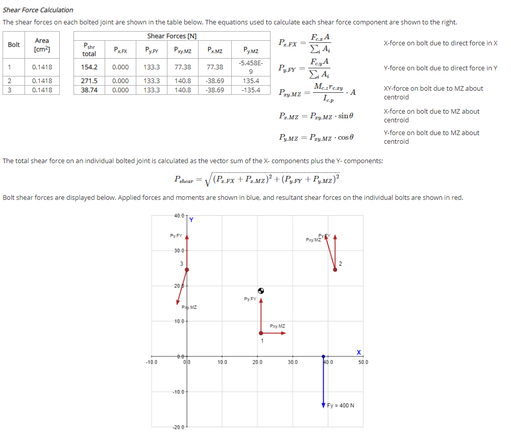
The direction of your resulting reaction forces appears wrong. The pull out forces, by inspection, should be -Z and vertical shear in +Y on all screws.
Since your simulation shows virtually no bending of the hinge and most of the stress at screw hole 1, I would treat this, as a first approximation, as a simple static problem and draw the free body diagram using the front elevation (posX view). Then, ignoring the kink in the hinge plate, you have a moment of the hinge load around the bottom edge of the back plate offset by two moments around the same point due to the fixing screws (lumping 2 and 3 together). Immediately, if the hinge pin load is in -Y, we can see that the reaction to all 3 screw ‘pull-out’ forces must be in the -Z direction as expected.
Taking the distances of the moments as roughly: hinge pin 45mm, screw hole 1 as 20mm and screw holes 2 & 3 as 40mm then:
Hinge pin moment: 0.045 x -400 = -18Nm
Screw hole moments: -(.02 F1 + .04(F2 + F3))
Assuming F2 = F3 (a good enough approximation ignoring hinge pin X offset) and, intuitively, (F2 + F3) = F1/2 we get:
-18 + -(0.02 * F1 + .04* F1/2) = 0 so F1 is 18/.04 = -450N and F2, F3 are -112.5N (i.e. all in -Z direction).
On that basis 3 off #10, 50mm long wood screws would give a >3x pull-out safety factor in a well seasoned wood frame. However, from a shear perspective I would use 5 screws to get the same safety factor.
Hi @atanas_kuzev an d @irving,
regarding the direction of the reaction forces, they are “correct” in both above simulations. And “correct” means “correct with respect to the simulation setup” - as they add up exactly to the inverse of external force.
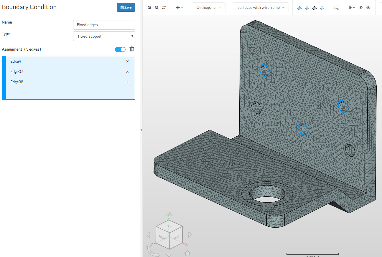
Of course, if the hinge behavior of the lower edges is not taken into account by the boundary conditions, you won’t see the expected behavior of that hinge. The initial setup was done in a way as there was no wall to which the back side of the screwed end was mounted.
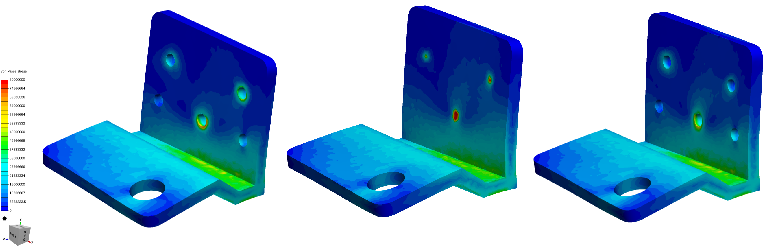
If we now add an additional constraint to the lower edge, fixing there the z-movement only, we get already “better” results:
Simscale
Rx, N
Ry, N
Rz, N
fix. edges
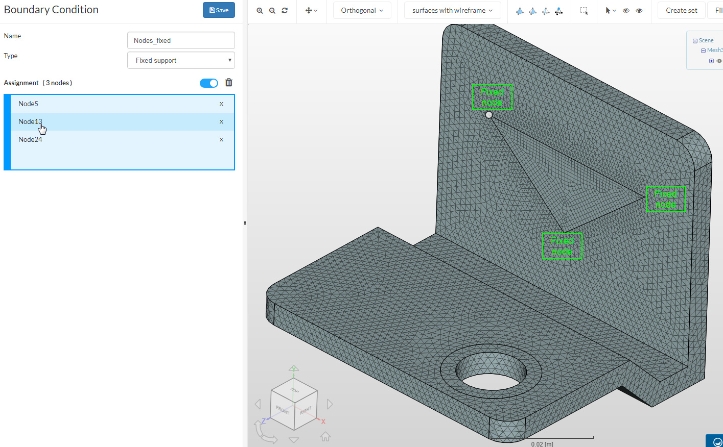
fix. nodes
remote fix
fix. edges
fix. nodes
remote fix
fix. edges
fix. nodes
remote fix
Screw1
144
105
155
212
208
279
-739
-543
-715
Screw2
104
13
181
191
220
162
-83
-103
-61
Screw3
-248
-118
-336
-3
-28
-42
10
-17
33
Σ*
0
0
0
400
400
399
-812
-663
-743
*: not total reaction forces as additional z-constraint is added to lower hinge edge
I added a third option (basically a mix of your existing options) by using the model with the holes, but putting a remote constraint (displacements fixed, rotations free) in each of the three holes instead of directly fixing the edges.
Interesting Richard. To my simplistic view I’d say the remote fix is closest, but even that doesn’t truly model the real-world situation.
Maybe another (arguably over-complex) way to model this is to add the door frame behind the hinge plate as a fixed entity having a distributed sliding frictional contact with the rear of the hinge plate, and model the screws as cylinders having a sliding/rotational contact withe inner faces of the holes and a fixed load on an annular ring around the screw hole to represent the head contact. This fixed load could be preset as the torqued-down pre-load on the screw heads before the door is fitted (i.e. choose a realistic screw size/material and see if the simulation ‘breaks’ it).
Defining the hinge pin load as 400N vertically is also a simplification, as in reality its a moment created by the mass of the door acting some distance from the hinge pin - though not as large as the moment on, and constrained by, the top hinge. To make the simulation truely accurate you should also run a time series as the hinge pin moment moves from being purely in the ZY-plane (door closed) to mostly in the XY-plane (door open 90 degrees).
Hi @rszoeke and @irving
First of all, thank you for the your replies and help.
I fully agree with your notes. Yes, it is very simple model and load, but my primary goal is to find only the reactions and compare them with those received from an online calculator:
I expected to get similar values. @rszoeke, from my point of view, there is a big difference between the values of reaction forces obtained from the different simulations. Besides, there is a big difference from the “analytical” solution.
The simulation of the full model and loads is the next step.
I tried a simplified version of your model, adding a frame and screws. As I expected the axial force on all three screws is out of the frame, not inwards for screw 1 as the website you linked to appears to suggest. The idea of using the centroid of the bolt pattern sort of makes sense but intuitively the hinge will rotate on its lower edge (and the simulation shows that’s a point of stress on the frame) and as long as the hinge plate is stiff enough there won’t be a moment around the centroid (IMHO).
My results are not accurate for your model but ~750N for screw 1 and 1/2 that for 2 and 3 is indicated.
I think, of the 3 choices, your #3 remote fix boundary conditions is certainly closer to reality.
I would like to see that with the 400N load applied to the inner quadrant of the existing load application circle since the door hinge pin would likely apply the full 400N there as soon as the hinge plat deforms under load (unless the pin is constrained by a loosely ‘bolted’ rotating tolerance ) .
Also I think a second Z constraint on the top edge of the screw plate would be in order.
If you get even fancier you could assume that the hinge plate is screwed into some sort of softwood and take into account how much the screws would pull out under load and how far into the wood that the top and bottom screw plat edges would sink into the wood under load
Where does overkill start
For practical design loadings I like Irvings last post but this topic is certainly showing me the possibilities of FEA for design use
Whilst I agree in principle, the simulation shows the horizontal element of the hinge only deflects about 0.07mm so I would still apply the force to the whole annular ring around the pin as I would intuit that the pin would also similarly deflect from the vertical under the load.
Why? There’s no force acting here and in the limit this would pull away from the frame. A sliding contact between hinge back plate and frame accurately models this relationship, giving vertical friction while in contact and no reaction once the gap exceeds the nominal 0.001mm tolerance.
I did think to try this but for it to be useful you have to model the screw threads and therefore make a design decision on the type of screw. Since there is a wealth of “screw-in-wood pull-out force tables” on the web so it’s easier to just model as a fixing and determine the reaction force then relate that back to the tables with an appropriate safety factor. Then you can trade off screw diameter v screw length. Turns out its the shear force that’s the more critical force.
Thanks Dale. Once you’d only consider FEA for major structural projects but with the advent of ease-to-use tools like this I find I’m using it all the time. I’ve even done a simulation of my soon to be erected garden room (a.k.a my home workshop) foundation slab to determine the optimum concrete/steel mix needed to cope with up to 4" of ground heave (I’m on London clay and near some trees). The result was a lot less steel in a more optimal structure and a less concrete but a stronger fibre-bonded mix than suggested by ‘rule-of-thumb’ tables and its going to work out at about 2/3 the cost! My wife says I’m obsessive but she’s not paying for it
I was not thinking that the pin could apply a vertical down load (even tho I said that ) , more the shoulder of the material that the pin protrudes from…
I am just not sure if the constrained hinge distortion does pull that edge away from the hinge mounting surface due to the constrainment from all the screws … could always just check to see if that edge did move away by looking at the sim results (but I would have to learn how to do that) … sometimes forces just propagate through multi-constrained systems in funny ways
I can see me doing just that and getting the same reaction from my wife