Project link: https://www.simscale.com/workbench/?pid=1804511658976461646&mi=spec%3A751d4862-44a0-43a7-a45c-bd1470f1cf48%2Cservice%3ASIMULATION%2Cstrategy%3A18
I am a beginner with this software and I am having a difficult time setting up a ventilation simulation in my project.
My project is a cluster of vernacular huts and I am studying the ventilation patterns in order to find optimal locations for inlets and outlets. I am currently using the convective heat transfer simulation to test this. I have set up an external flow volume through the software, but I am still having trouble fully understanding how this works ( so their might be error in that part). I modeled my design in rhino, and to keep my project as clean as possible, I Boolean differenced my project into a solid block in order for simscale to process my project as one whole solid.
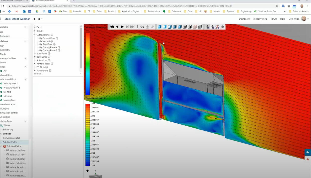
My end result wants to look like this. (look at timestamp 21:00)
https://www.youtube.com/watch?v=kxAYoL072V0&ab_channel=SimScaleGmbHSimScaleGmbH
I would appreciate any help with how to finish out this study! Thanks!
Hello @krazycyle ,
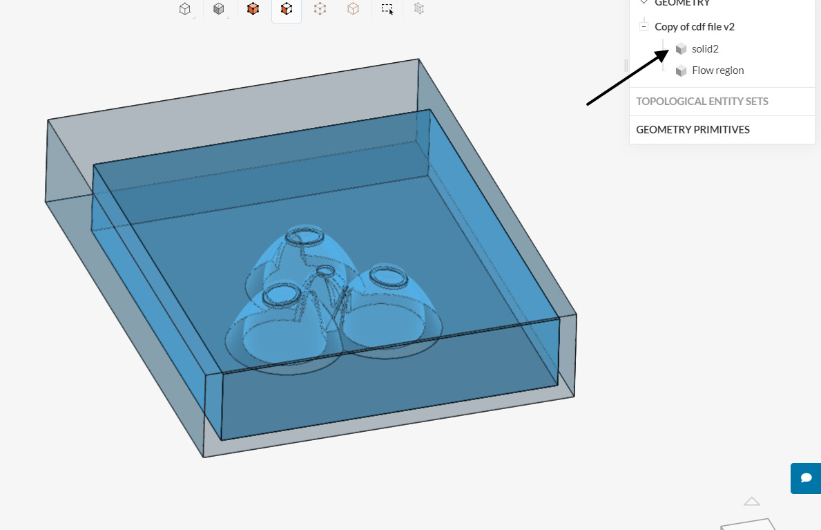
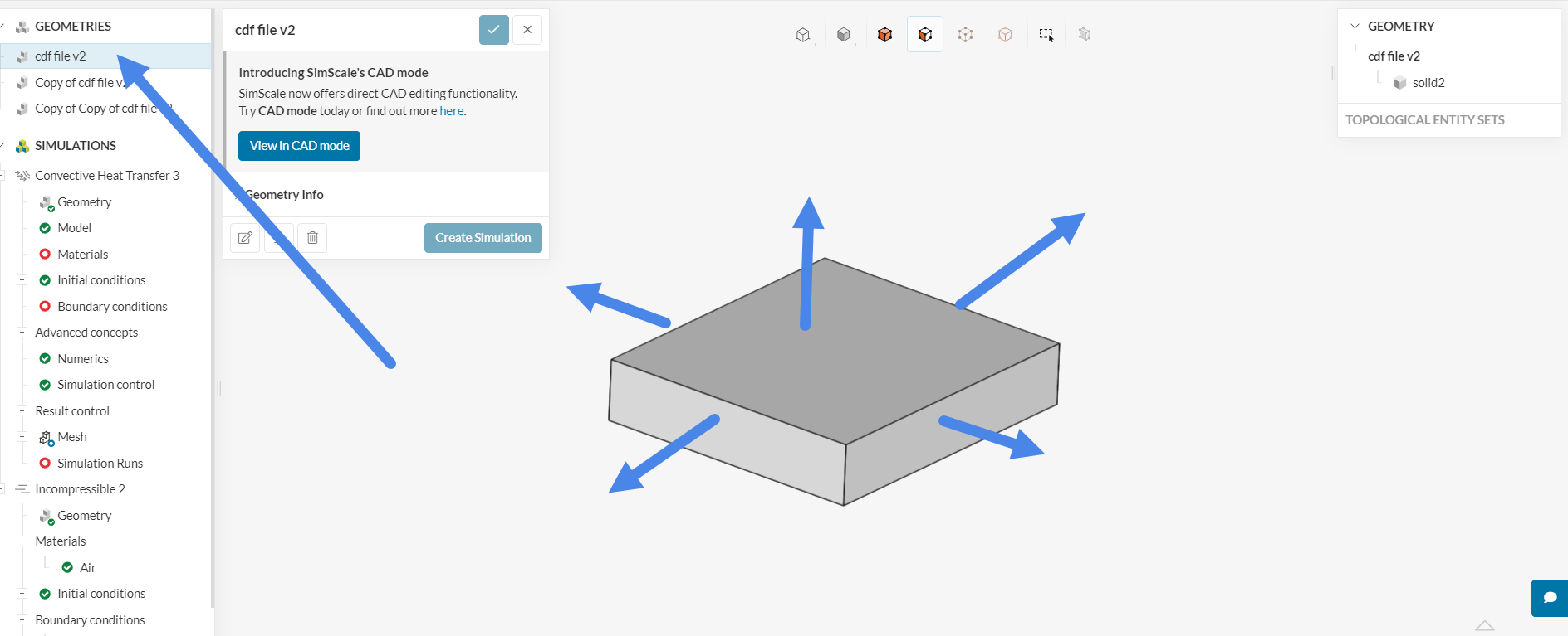
As we had previously discussed, the first step for this particular analysis was to create the flow region in Rhino. With that said, if you create the flow region locally in Rhino, it is no longer necessary to create it again in SimScale.
Therefore, “solid2” is the only volume you need to run the simulation:
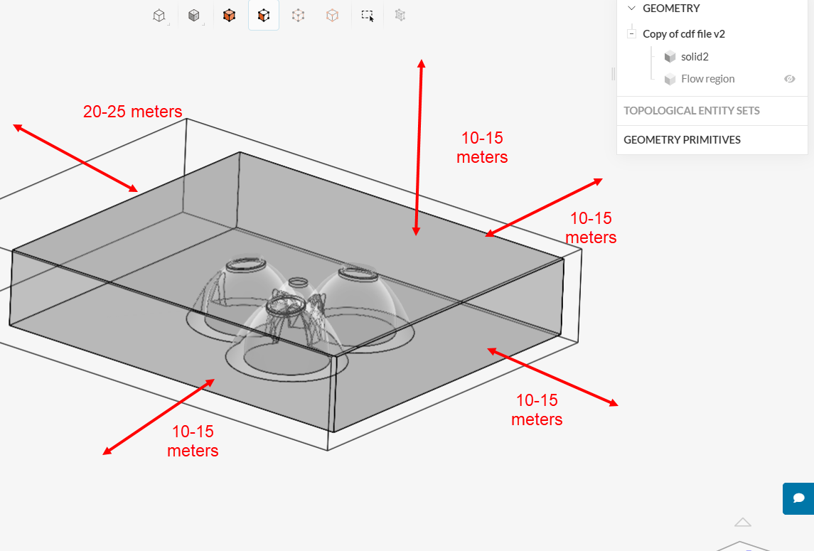
Just one comment, the current flow region looks a little small - it would be best to extend its boundaries a little further out. I’d recommend extending the top, sides and inlet (i.e. upstream from the model) by 10-15 meters, and extending the flow region downstream by 20-25 meters:
Now, you mentioned that you are currently using a convective heat transfer analysis. One question: are you going to model any heat being dissipated in the model? (e.g. a human inside the “huts”?) Or is the entire domain going to remain at the same temperature?
Ultimately, I would like to test how the internal heat dissipates, so yes, I do need to place humans inside to study its effect.
However, right now I want to study external wind ventilation to find out where to place windows in the huts. How should I set up the model so I can visually see wind patterns like this image?
If you are only interested in the flow patterns for the moment, it would be best to go for an “Incompressible” analysis.
In the future, if you want to study temperatures as well, then a convective heat transfer analysis would be the way to go.
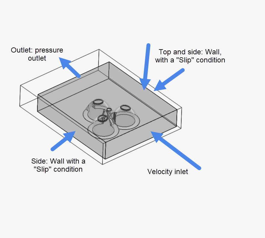
After you make the domain a little wider (as per my previous post), the usual BC configuration is the following:
As far as meshing goes, I’d say that a hex-dominant mesh would still work best for this particular model.
Ok so I reset the domain, added the boundary conditions, and rendered the hex dominant mesh. What is needed next?
Ops, I may not have been clear enough in the previous post:
- The external flow volume operation no longer needs to be run in SimScale, since you have already created the flow region locally in Rhino (we don’t need to create the flow region twice, if it makes sense).
So, the original .3dm file should be the one getting its boundaries extended:
After importing the new .3dm file to SimScale, it’s not necessary to run any additional operations, it will already be good to simulate.
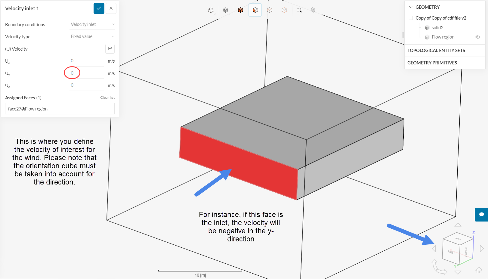
As far as boundary conditions go, it’s very simple. Below we have the inlet:
The outlet is a simple “Pressure inlet” (and not a velocity inlet). And you already have the “Wall - Slip” correctly created. Note that only the 2 sides and the top (sky) faces should be defined to the slip condition.
Then it’s just a matter of pressing start to run the simulation 
What do I set the bottom wall to? (i.e. wall-noslip?) And do I set need to generate the mesh?
All faces which are not assigned to any boundary conditions automatically receive a no-slip condition. So don’t worry about that.
I’d just go with a default hex-dominant mesh for the initial simulation, just to get a feeling for mesh size and mesh quality.
Naturally, you will have the option to make changes once you get the first simulation in. (e.g. surface/region refinements)
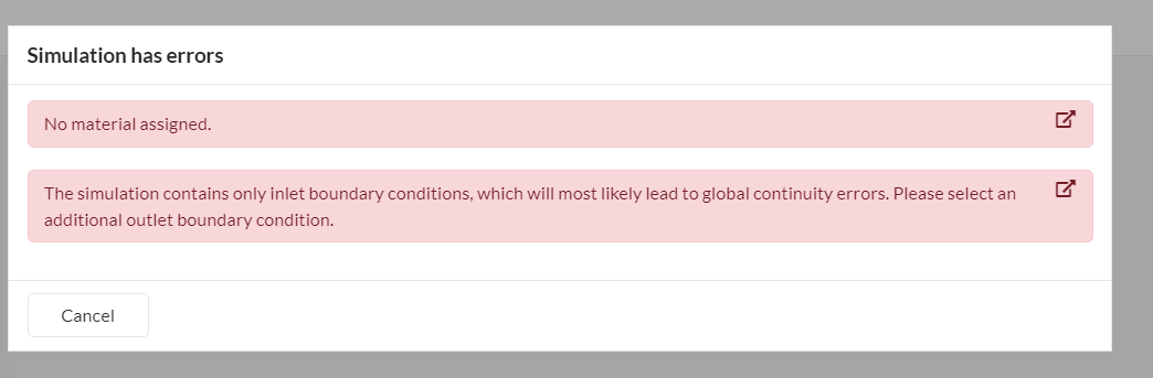
I am getting this error message when hitting simulation run
The extended model would work better, but anyway…
The error messages are clear: there is no material assigned to the flow region (one material needs to be assigned);
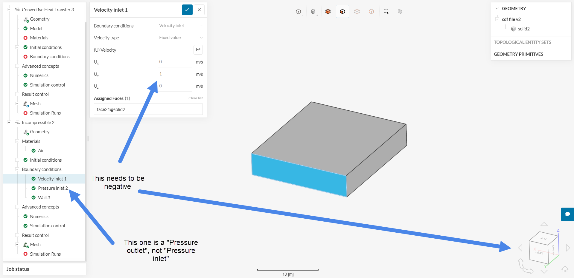
There is no outlet defined (currently we have a ‘pressure inlet’ instead of pressure outlet):
Also note that the velocity should be in the negative y-direction, to act as an inlet. So it’s -1, and not 1.
Ok thank you, it is working now! It also said that i needed to add materials to the model. Should I set the material to air? And if so do I need to change any properties of the air material?
Yes, the material would be air. Changing the default properties is possible (but naturally this is not up for me to decide).