I’m trying to set up a CFD simulation with (at least initially) some simplified ‘trees’ which are supposed to be porous. However, I’ve tried several different options and can’t really get to create a mesh that includes both the ‘enclosure’ and the ‘tree’ regions (the cylindrical ‘trunk’ pieces are supposed to be left empty), and I can either get a mesh of everything, of the enclosed space (without the trees) or an error.
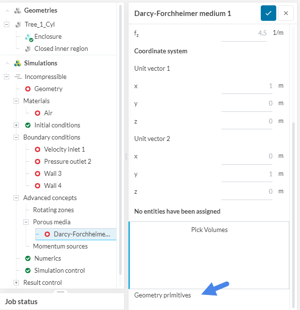
For this simplified geometry, there’s a very straight forward way to configure the porous zones. You can use geometry primitives instead of adding volumes in your CAD geometry to represent the trees:
However, this will only work with simplified geometries for the trees. More specifically, with cubes/parallelepipeds, cylinders and spheres.
Since you're planning to use more complex trees, I'll describe the "more complete" way, which works for all cases. The steps are:
1- In your CAD software, start with the tree volumes (both trunk + leaves);
2- The key point here is that you’ll have to create the enclosure in your CAD software. Create a simple enclosure, 100% solid. You shouldn’t use any boolean/subtract operation here. The enclosure and the trees should fully intersect with each other;
3- Bring this geometry to SimScale. As you have already created the flow region in your CAD software, you can proceed to create a simulation;
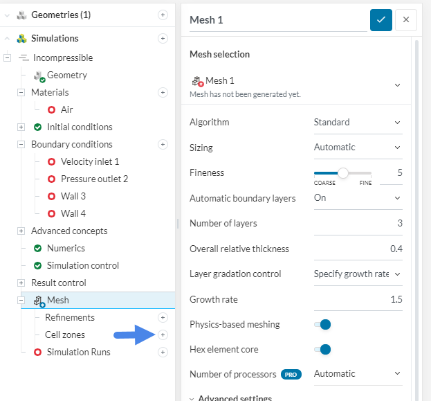
4- In the meshing operation, there’s a mandatory step. You need to declare the tree volumes as a “Cell zone”. For a standard mesh, creating a cell zone is pretty straight forward: