I created a new simulation project called 'Garage with ventilation':
Geometry from Onshape: https://cad.onshape.com/documents/9db2bc5d5b100083579ded2b/w/0d763bb26dc168655944c0bf/e/29b709943aebeb6bf3a00d4a
More of my public projects can be found here.
CFD simulation of a garage with Momentum Sources.
Overview
Withing this project I present the way of inserting momentum sources to a CFD simulation.
Momentum sources can be interpreted as virtual areas within the flow that force the fluid to move in a particular directions.
Typical application is to use them as models for standard flow agitating objects, such as fans, jets, etc. Thanks to the use of momentum sources engineers do not have to directly model the fan (mesh the blades, add rotating zones).
A tempting alternative to momentum sources would be to use “black boxes” which would have suction outlets on one side and velocity inlets on the other. The problem with this approach is that it does not allow for transport of flow relevant quantities, such as passive scalars or heat.
In this project I used Incompressible turbulent flow model, but same methodology can be applied to passive scalar or flow heat transfer simulations.
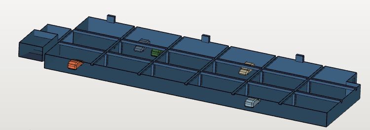
The geometry
The geometry of the garage was prepared in Onshape and can be found at this link:
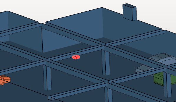
It consists of the volume extract of the air inside the garage, 5 car models parked inside and an additional solid box that will represent one of the momentum sources.
The mesh
The meshes for simulations with momentum sources work the same way as standard CFD applications.
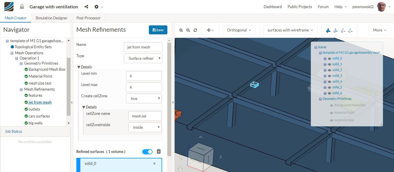
An extra step can be taken if you require extra mesh quality around the momentum sources. In that case you will need to specify the position of the momentum source in the CAD. In principle any object that is not the air domain is considered to be a flow obstacle (refer to the models of the cars). Things are different if you apply special refinement type: **Surface Refinement with Creation of Cell Zones** . In that case the object gets meshed inside, and fluid volumes inside are grouped into a mesh entity with a given name. (this is the same methodology as if creating rotating zones)
The simulation
Overall the simulation setup for analysis that includes momentum sources is very similar to a standard flow analysis. Momentum sources are added under **Advanced Concepts**.
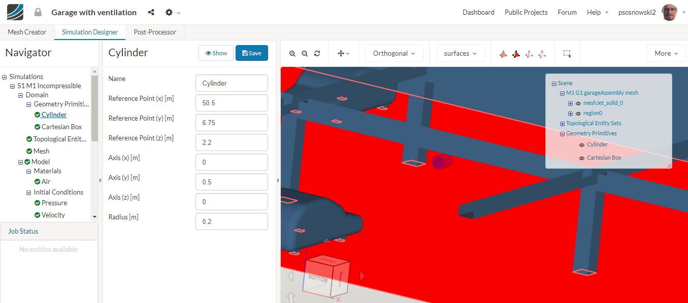
The sources can be assigned to two entity types:
a) to _cellZones_ created during meshing
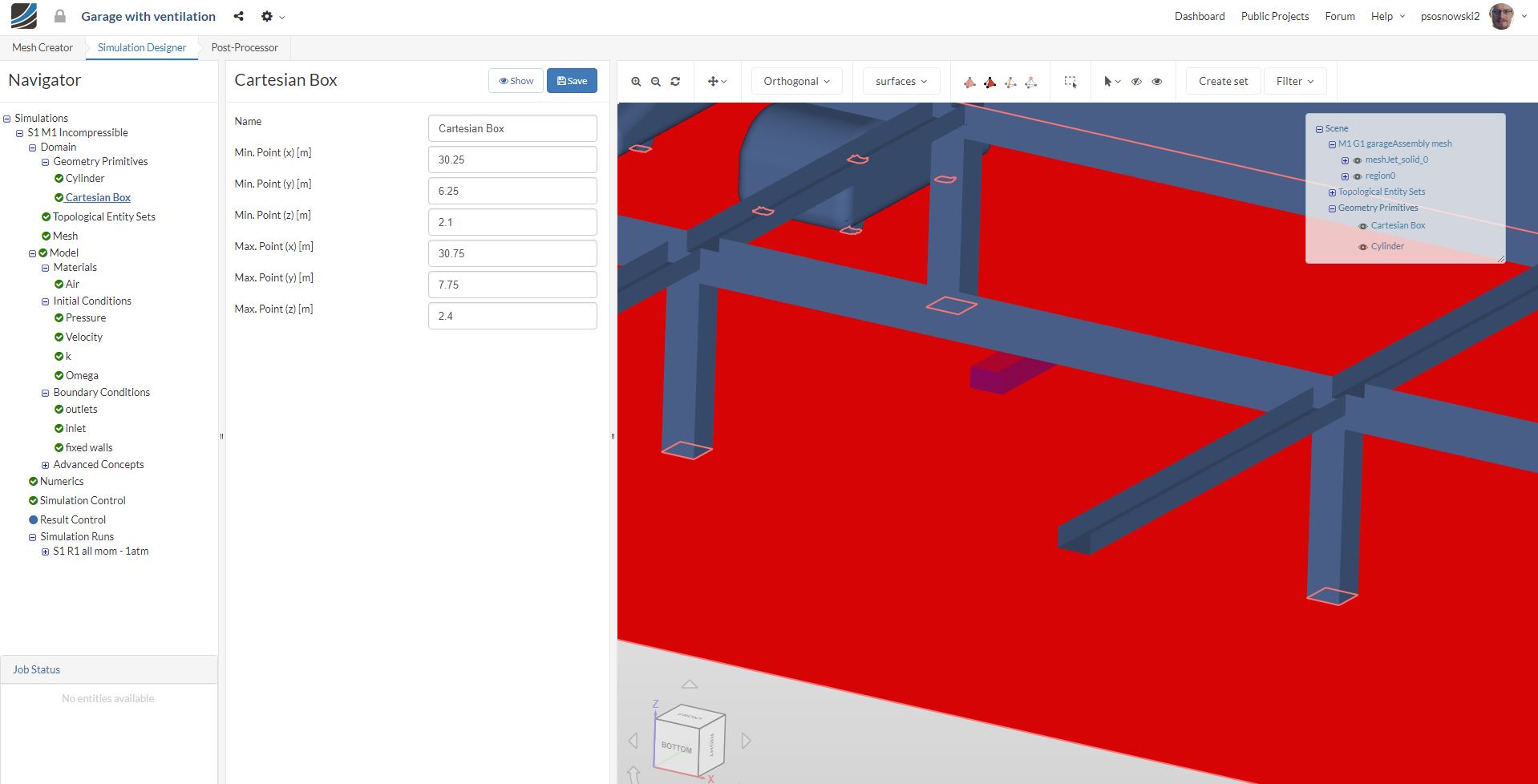
b) to_Geometry primitives_ such as boxes and cylinders created in in the simulation setup
Advantages of cellZone approach and Geometry primitives approach
- When you decide to use cellZones, you will obtain better control over mesh quality at the momentum source. You can exactly restrict its presence to a given location
- Geometry primitives will use the existing, underlying mesh to generate the momentum source. If the mesh is coarse in selected area, the source will be not precisely defined
- On the other hand, not having to re-mesh the project when using Geometry Primitives makes them perfect choice for preliminary studies of the problem.
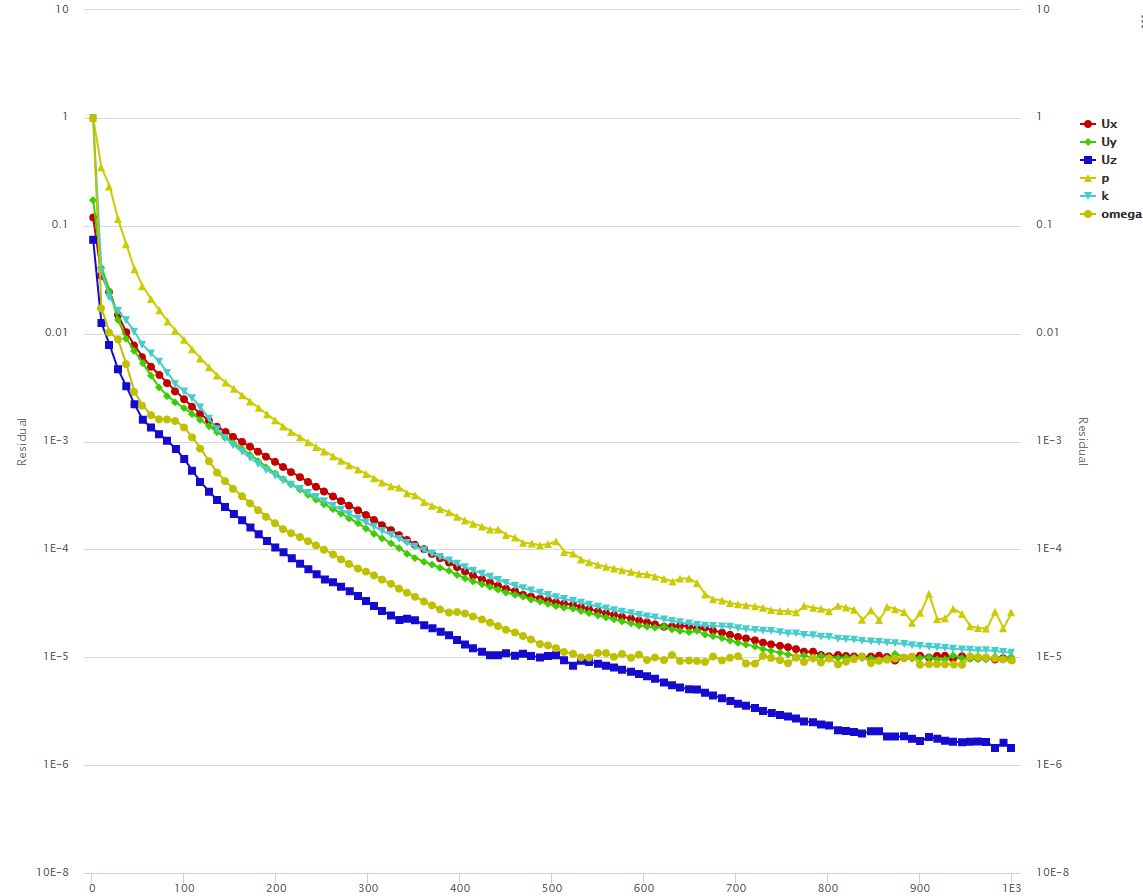
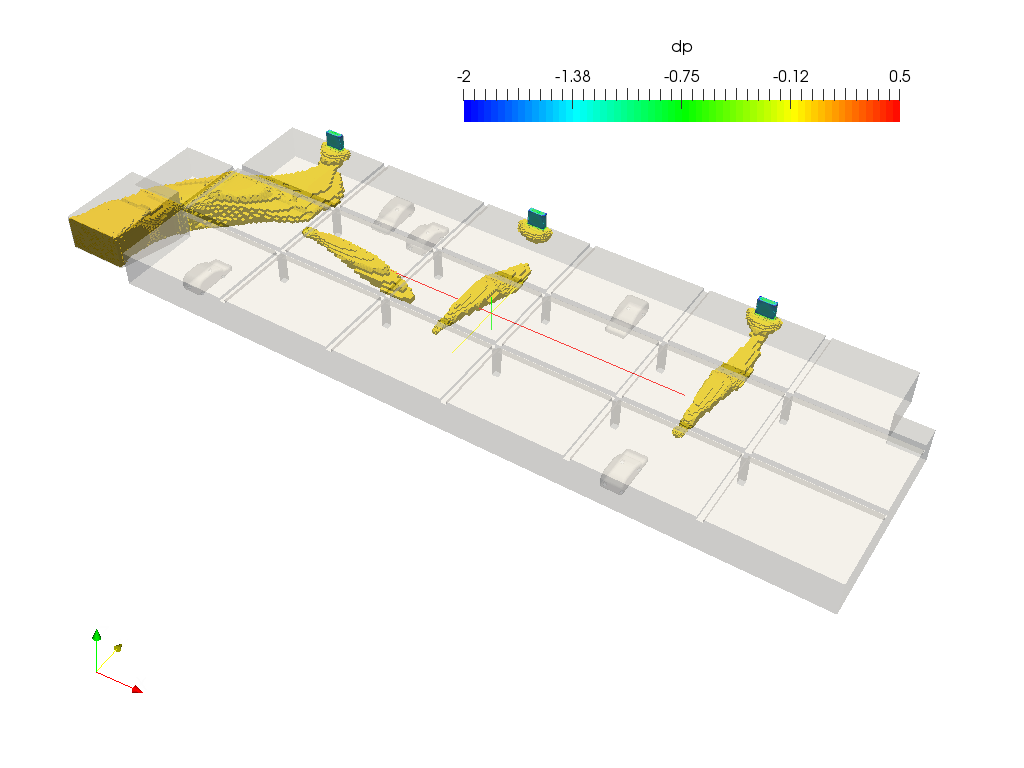
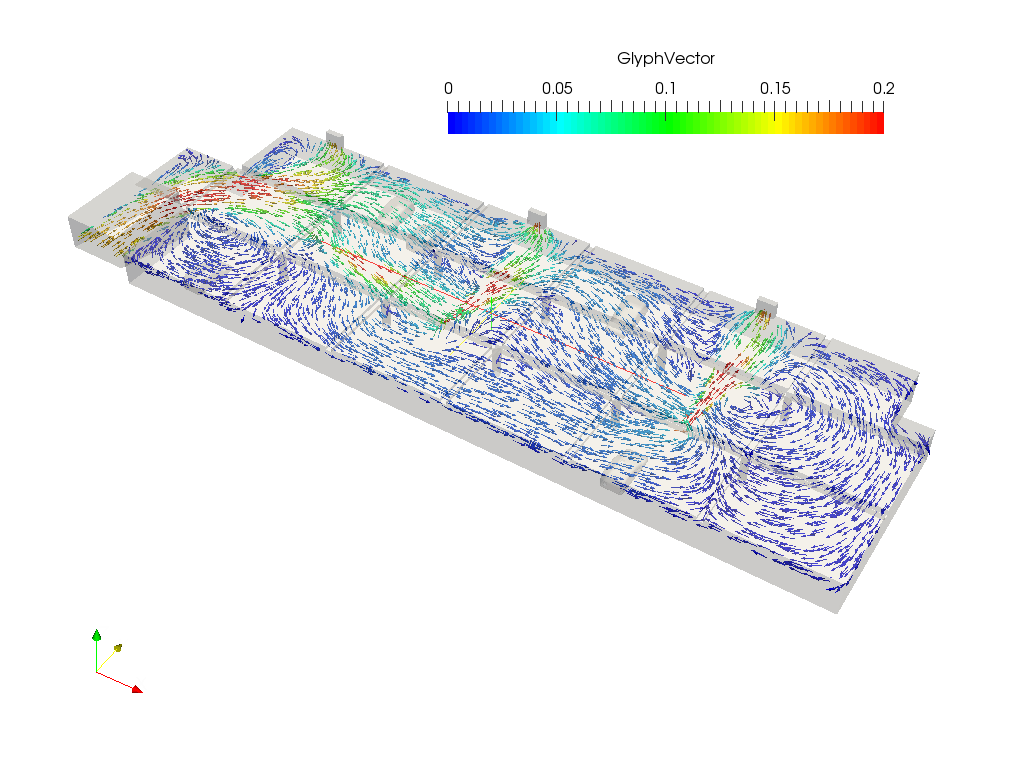
Simulation results
The analysis including momentum sources will behave in a similar fashion to a standard simulation. Still, the results will include the extra flow effects generated by the momentum sources. The post processing images below present the areas of high velocity and the flow vectors at the momentum source level. You can clearly see the extra momentum generated by the sources.
Hope you like this project. Leave a comment if you have any questions!
4 Likes