Good morning,
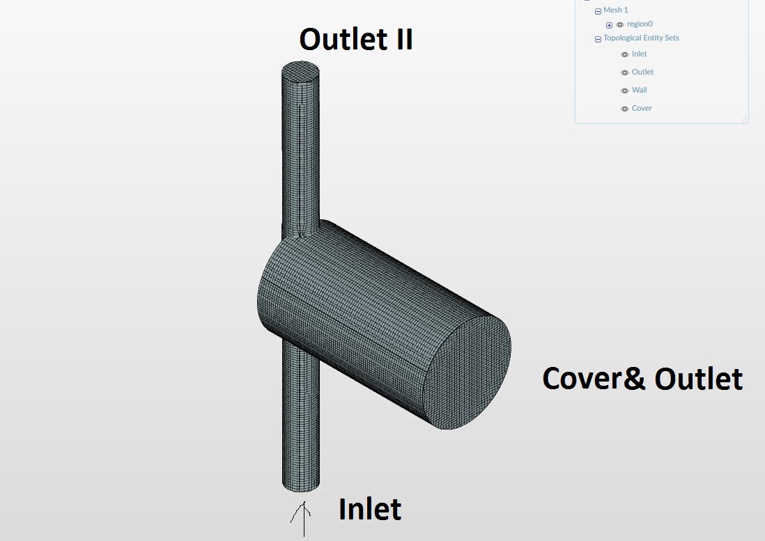
id like to simulate the multiphaseflow in a sewer shaft. I make a simple test [project].
The simulate works, but no water flows out of the pipe. I tried different boundary conditions but no one works.
Which boundary condition should i use to creat a free flow out of the pipe ?
Furthermore i have another question, what does Phase fraction value mean ? I read the documentation, but i dont understand it.
If Water is phase 1 and air is phase 0.
Means Phase fraction value 0 at a Boundary conditions that only air (Phase 0) can go out at this Boundary ?
Run 8 10 sec 1 m/s
Cover&Outlet and Outlet II at the same Boundary condition.
Type: Custom
Velocity: Pressure-inlet-outlet velocity
Pressure: Total pressure
Phase fraction: Fixed value
Phase fraction value: 0
It works, but no water flows out at Outlet II.
Run 8/a
Cover&Outlet
Type: Custom
Velocity: Pressure-inlet-outlet velocity
Pressure: Total pressure
Phase fraction: Fixed value
Phase fraction value: 0
Outlet II
Type: Pressure outlet
Pressure: Fixed value
it dosent work…
Run 8/b
Cover&Outlet
Type: Custom
Velocity: Pressure-inlet-outlet velocity
Pressure: Total pressure
Phase fraction: Fixed value
Phase fraction value: 0
Outlet II
Type: Custom
Velocity: Pressure-inlet-outlet velocity
Pressure: Total pressure
Phase fraction: Fixed value
Phase fraction value: 1
Hi Kai (@Kai_himself) and thanks for the detailed description of your problem!
Looks like a very interesting project! Either the Community or me will get back to you asap with some tips on how to improve your simulation to get some good results.
So far I haven’t been able to get a simulation that doesn’t run into fatal instability but I think I have made more refined mesh that would give you rather accurate results if provided you can get the simulation running. You can see it [here] under “Barry Mesh”. The mesh is quite well refined with proper boundary layer inflation internally and you can see that as well at the inlets and outlets so it should be usable.
@jousefm Looks like I won’t be able to tackle this but regarding the phase fraction value I assume it has to do with the amount of “material” of which type that goes into the inlet? Example, if the phase fraction value is 0.5, half is water and the other half is air? Also you might need to call someone more familiar with multiphase flow
In general the multiphase flow analysis is carried out using the so called VoF (Volume of fluid) method which is a standard approach for the computation of multiphase systems (another approach would be SPH (Smoothed Particle Hydrodynamics)).
The basic principle of this method is to give each control volume a specific fraction of fluid, where Alpha defines the volumetric phase-fraction:
Alpha = 1 : Domain only filled with liquid
Alpha = 0 : Domain only filled with gas
0 < Alpha < 1 : Control Volume contains gas as well as fluid which can be interpreted as the phase boundary between the two fluids.
As Barry mentioned correctly, 0.5 means that we have 50% liquid and 50% gas inside the control volume. If you define your inlet let’s say as an inlet for liquid there is only liquid and no gas. Coming back to your initial question @Kai_himself you are right that a phase fraction value of 0 at the outlet is a restriction for the liquid not to flow outside the domain.
Edit: Let me get back to you asap and think about this again as there could be physical setups where - although you have a fraction of 0 at the outlet - still have fluid being emitted.
Hello,
so i try your Mesh, unfortunately they dont work until the end.
If the input phase fraction value is 0 (Air) the sim will run until the end, but is it 1 (Water) they get stuck often at 1.5 seconds (app. 31%).
I tried to creat a tabel with the Boundary Conditions of all runs.
Hi @all,
so i tried a few more simulations runs with different Solver and boundary conditions, unfortunately it also dosent work.
I think i get good results with the following boundary setup. Einlauf Velocity inlet 1,5 m/s; Auslauf unten Velocity outlet 1,5 m/s; Auslauf oben Pressure outlet (usally the Water dont get to it).
But an Error occured at 99% ;(.
After that i tried different Solvers, this ist the template for it, but it also dosent work well.
Often velocity inlet&outlet definitions won’t work and it is better to define a pressure outlet definition. Also could not run it with the settings you did. Running some simulations later on and getting back to you asap.
I’ve had a hand on a few multiphase flow projects so I think I might know the issue!
But before this, a quick question regarding the inlet. Is it supposed to be purely water? Or is there supposed to be some mix of water and air both coming through the inlet?
Do you intend to have some sort of water flow at like half of the pipe rather than the whole circular inlet? Or is it supposed to be fully water? I’m thinking somewhat like how a pipe with a hole might work and that over time it may “fill up” if set wrongly giving you your error.
As for now, try setting “Cartesian Box Grundfüllung” to encompass the entire circular inlet and outlet and see if that works.
The simulation is about the turbulence created in the shaft area. I think a cicular inlet ist ok, but it try it with the box and after that i will test it with the pipe.
@Get_Barried, @jousefm,
Thank you for your help.
The simulation run with the pipe full of water at the start works ! So i can go on with more simulations
Why does an error occured if its not full of water ? It is because the two Alpha phases touches the outlet, like in my picture?
Glad that solution worked! Hopefully your simulations run as expected. If there are any issues we can always tackle them.
I suspect this is just a simple case of the solver getting confused. If you remember previously your entire circular inlet was defined as water while your box was merely half of the circular inlet. The solver needs to know where water can go and by “placing water outside” of the defined area where water should be flowing, the solve got confused and just output an error. At least, that was what I was thinking when I saw the issue.
No not really this shouldn’t be an issue. This would only be a concern if you had to define two inlets (in your case your inlet is only water), one for air and water at say half of the inlet (example, upper half of the inlet is air and the other lower half is water). Then defining our water domain as you have done before the fix would be correct.