I created a new simulation project called 'fp-024a - Sidepod / Radiator':
Simulation Control Data forked from fp-023d
More of my public projects can be found here.
I created a new simulation project called 'fp-024a - Sidepod / Radiator':
Simulation Control Data forked from fp-023d
More of my public projects can be found here.
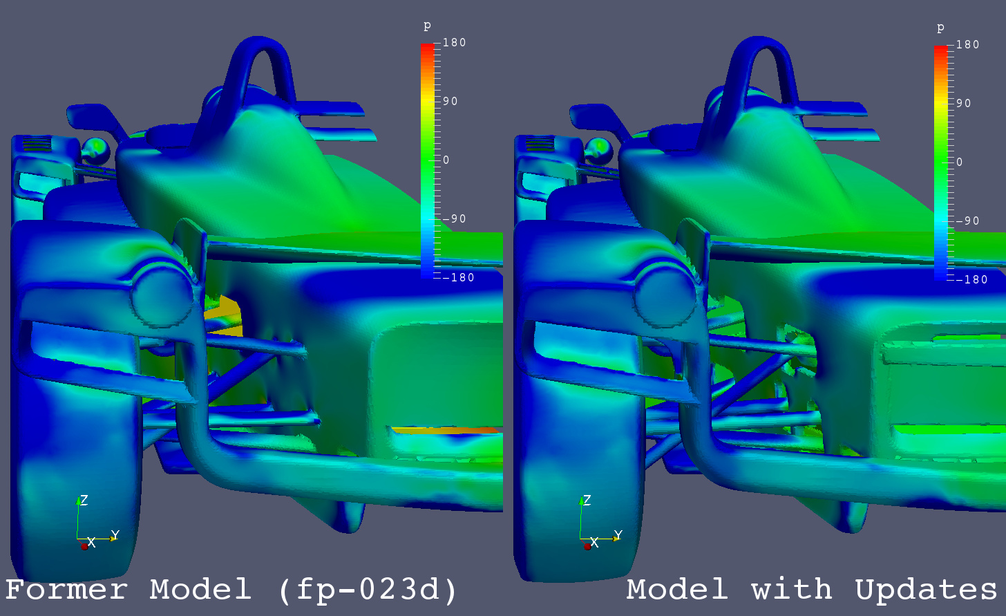
I rebuilt a CFD model with mechanical design updates.
The bodyworks are basically the same with the former model in fp-023d simulation.
Major changes are as follows.
Coefficients of Forces on Body and Wheels
| Coef. | Control | Model with Updates | Difference | Difference % | Remarks |
|---|---|---|---|---|---|
| Cm | 0.0518 | 0.0352 | -0.0166 | -32.1 | |
| Cd | 0.5649 | 0.5637 | -0.0013 | -0.2 | |
| Cl | -0.2135 | -0.1795 | 0.0340 | -15.9 | |
| Clf | -0.0550 | -0.0546 | 0.0004 | -0.7 | |
| Clr | -0.1586 | -0.1249 | 0.0336 | -21.2 | |
| CoP | 0.7425 | 0.6959 | -0.0466 | -4.7 | |
| L/D | -0.3780 | -0.3185 | 0.0595 | -15.7 |
Coefficients of Forces on Body Only (without Wheels)
| Coef. | Control | Model with Updates | Difference | Difference % | Remarks |
|---|---|---|---|---|---|
| Cm | 0.0282 | 0.0099 | -0.0184 | -65.1 | |
| Cd | 0.4531 | 0.4545 | 0.0014 | 0.3 | |
| Cl | -0.2557 | -0.2176 | 0.0381 | -14.9 | |
| Clf | -0.0996 | -0.0989 | 0.0007 | -0.7 | |
| Clr | -0.1561 | -0.1186 | 0.0374 | -24.0 | |
| CoP | 0.6104 | 0.5453 | -0.0651 | -6.5 | |
| L/D | -0.5643 | -0.4786 | 0.0856 | -15.2 |
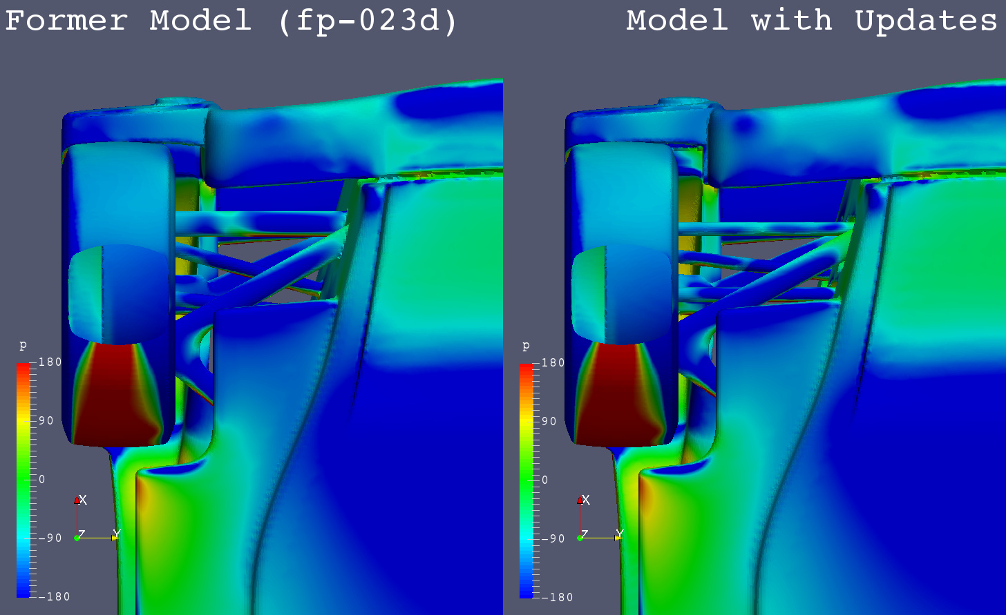
The drags and the front downforces are almost the same, but the rear downforce decreased significantly at the model with updates.
Some low pressure areas are decreasing on the bottom side of the stepped floor and the rear bumper.
Although the rear downforce is decreasing, since it is a model which the car designs are more applied to, simulations will be based on this model afterwards.
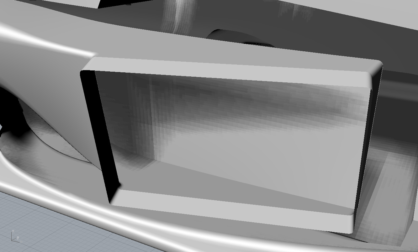
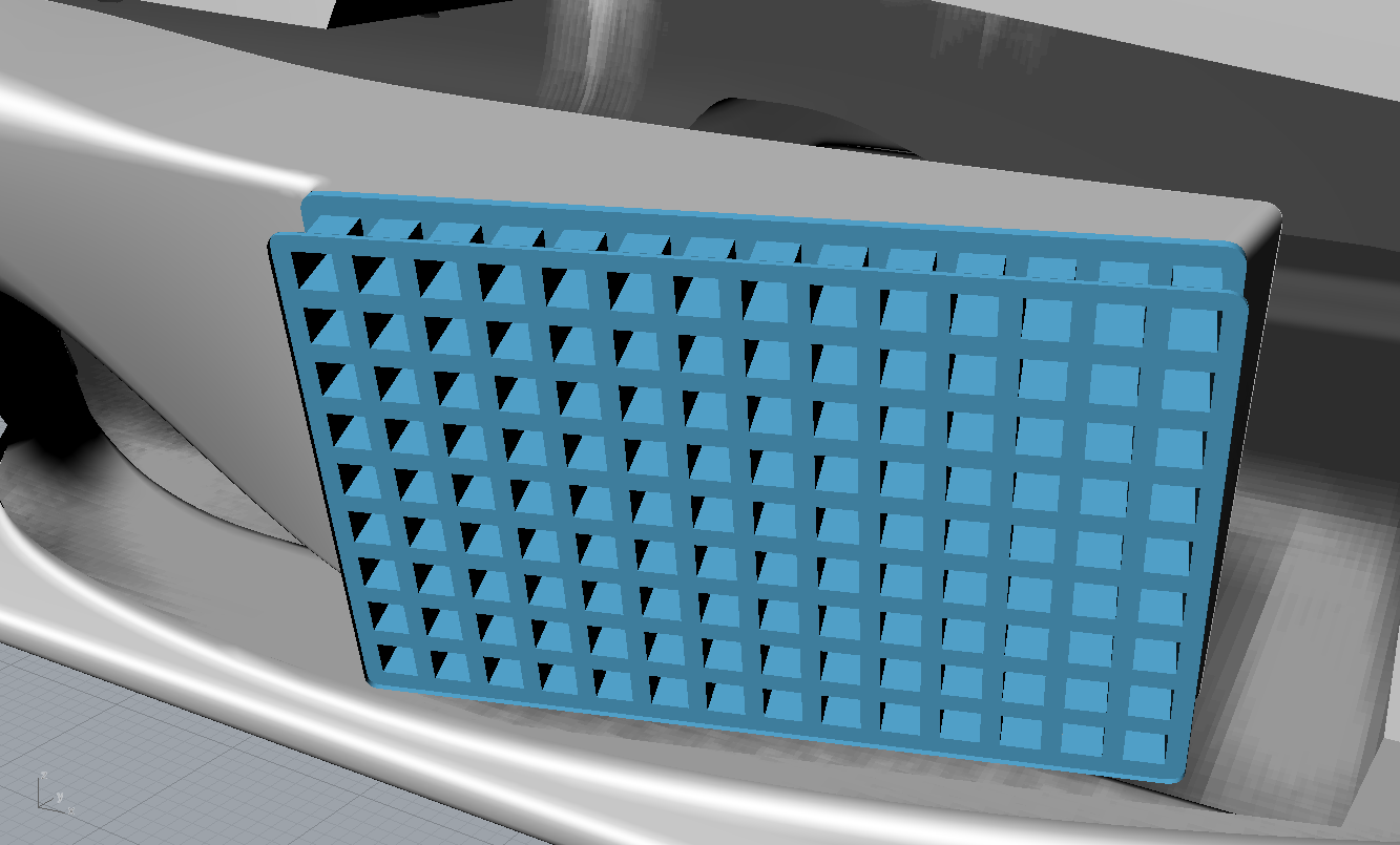
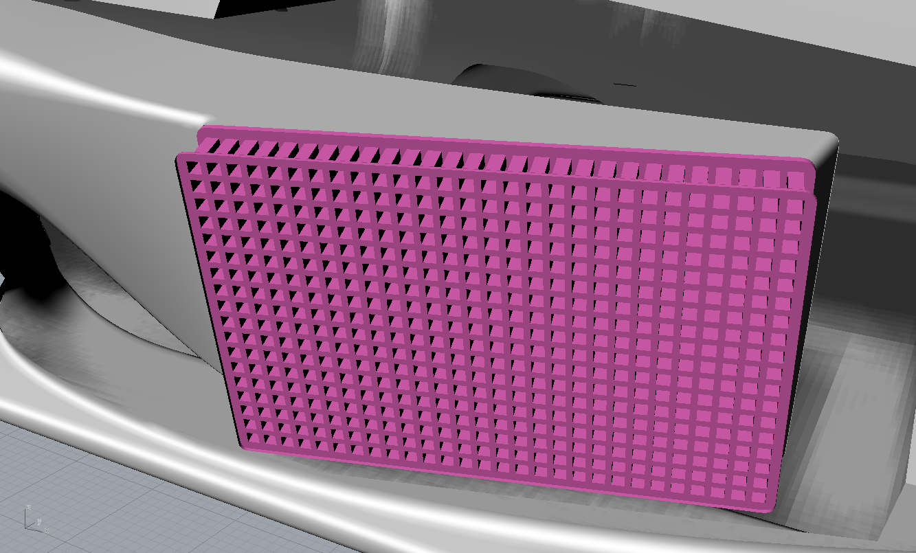
I tried to set porous media as a radiator simulation model, but I failed to make ‘cellZone’ for porous media in my project. So I made simple radiator models with many square holes.
Radiator Model - None : Control
Radiator Model - 20mm x 20mm Holes
Radiator Model - 10mm x 10mm Holes
Coefficients of Forces on Body and Wheels
| Coef. | Control | Difference | 20mm x 20mm | Difference | 10mm x 10mm | Remarks |
|---|---|---|---|---|---|---|
| Cm | 0.0352 | 0.0001 | 0.0353 | 0.0003 | 0.0356 | |
| Cd | 0.5637 | 0.0001 | 0.5637 | 0.0000 | 0.5638 | |
| Cl | -0.1795 | -0.0014 | -0.1810 | 0.0004 | -0.1806 | |
| Clf | -0.0546 | -0.0006 | -0.0552 | 0.0005 | -0.0547 | |
| Clr | -0.1249 | -0.0008 | -0.1258 | -0.0002 | -0.1259 | |
| CoP | 0.6959 | -0.0009 | 0.6950 | 0.0022 | 0.6973 | |
| L/D | -0.3185 | -0.0025 | -0.3210 | 0.0007 | -0.3203 | |
| RF | 0.2057 | -0.0298 | 0.1760 | -0.0403 | 0.1357 | Radiator Flow m3/s |
| RF | 1.0000 | -0.1447 | 0.8553 | -0.1957 | 0.6596 | RF / Control |
Coefficients of Forces on Body Only (without Wheels)
| Coef. | Control | Difference | 20mm x 20mm | Difference | 10mm x 10mm | Remarks |
|---|---|---|---|---|---|---|
| Cm | 0.0099 | 0.0002 | 0.0101 | 0.0003 | 0.0104 | |
| Cd | 0.4545 | 0.0002 | 0.4548 | 0.0000 | 0.4548 | |
| Cl | -0.2176 | -0.0014 | -0.2190 | 0.0002 | -0.2188 | |
| Clf | -0.0989 | -0.0005 | -0.0994 | 0.0004 | -0.0990 | |
| Clr | -0.1186 | -0.0009 | -0.1196 | -0.0002 | -0.1198 | |
| CoP | 0.5453 | 0.0008 | 0.5461 | 0.0016 | 0.5476 | |
| L/D | -0.4786 | -0.0029 | -0.4815 | 0.0005 | -0.4811 |
Much smaller size of square holes like 5mm x 5mm needs meshes to be smaller by one step more.
Therefore, at the present stage, I test aerodynamic devices about the sidepod and radiator
with the radiator model of 10mm size square holes.
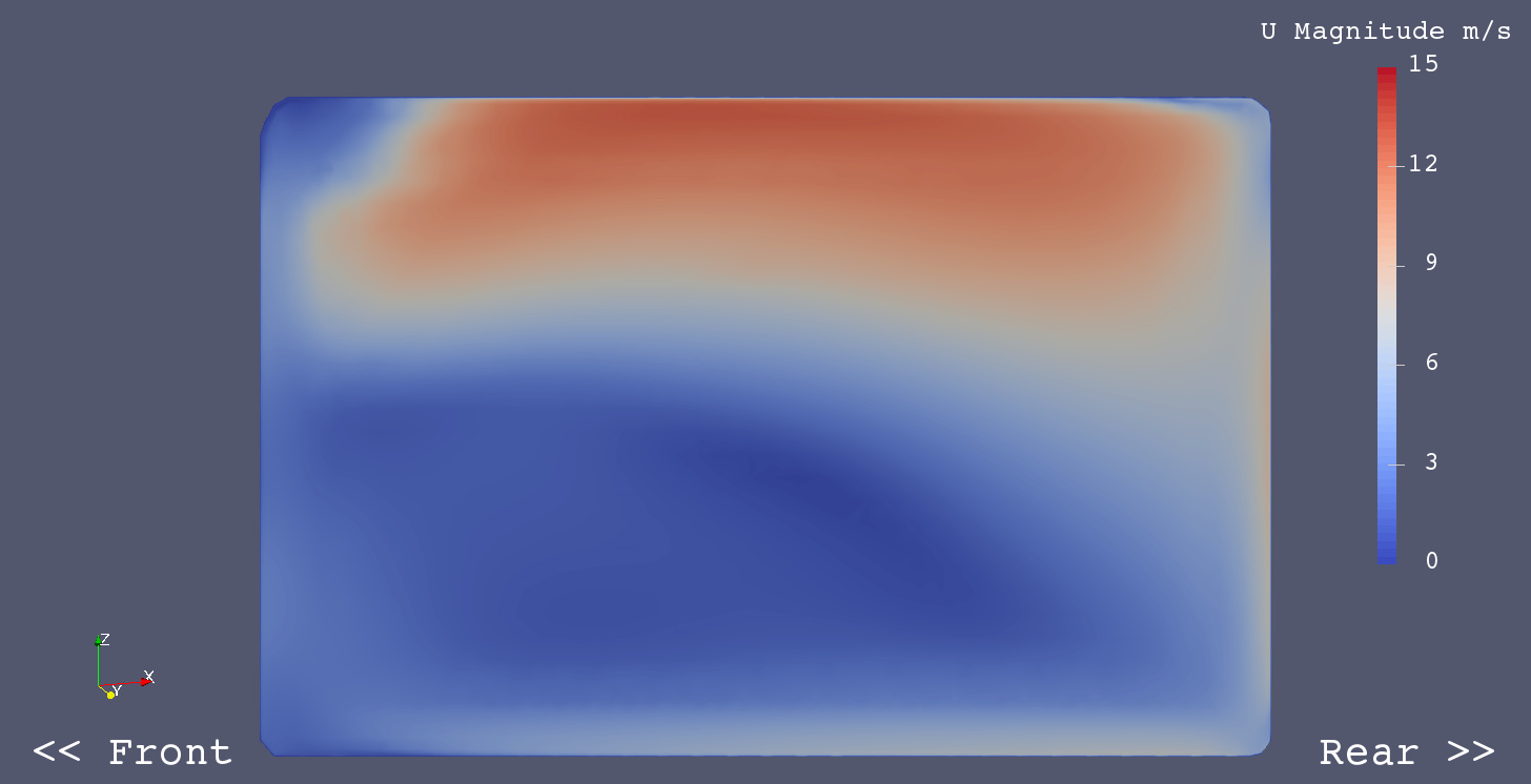
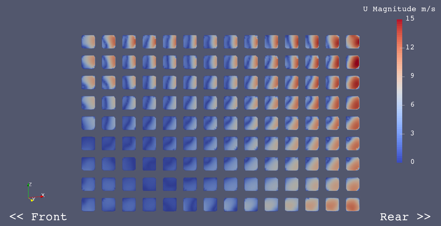
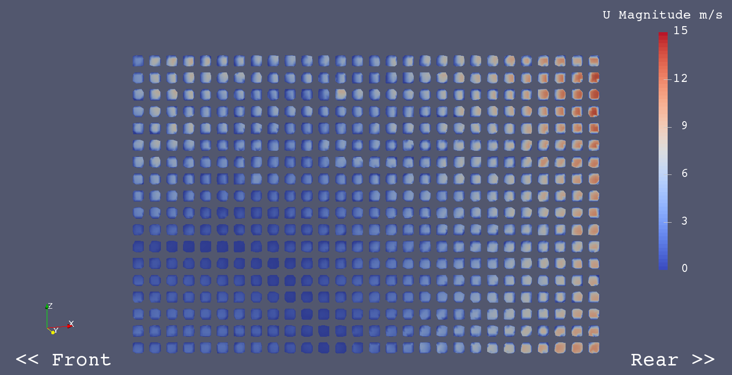
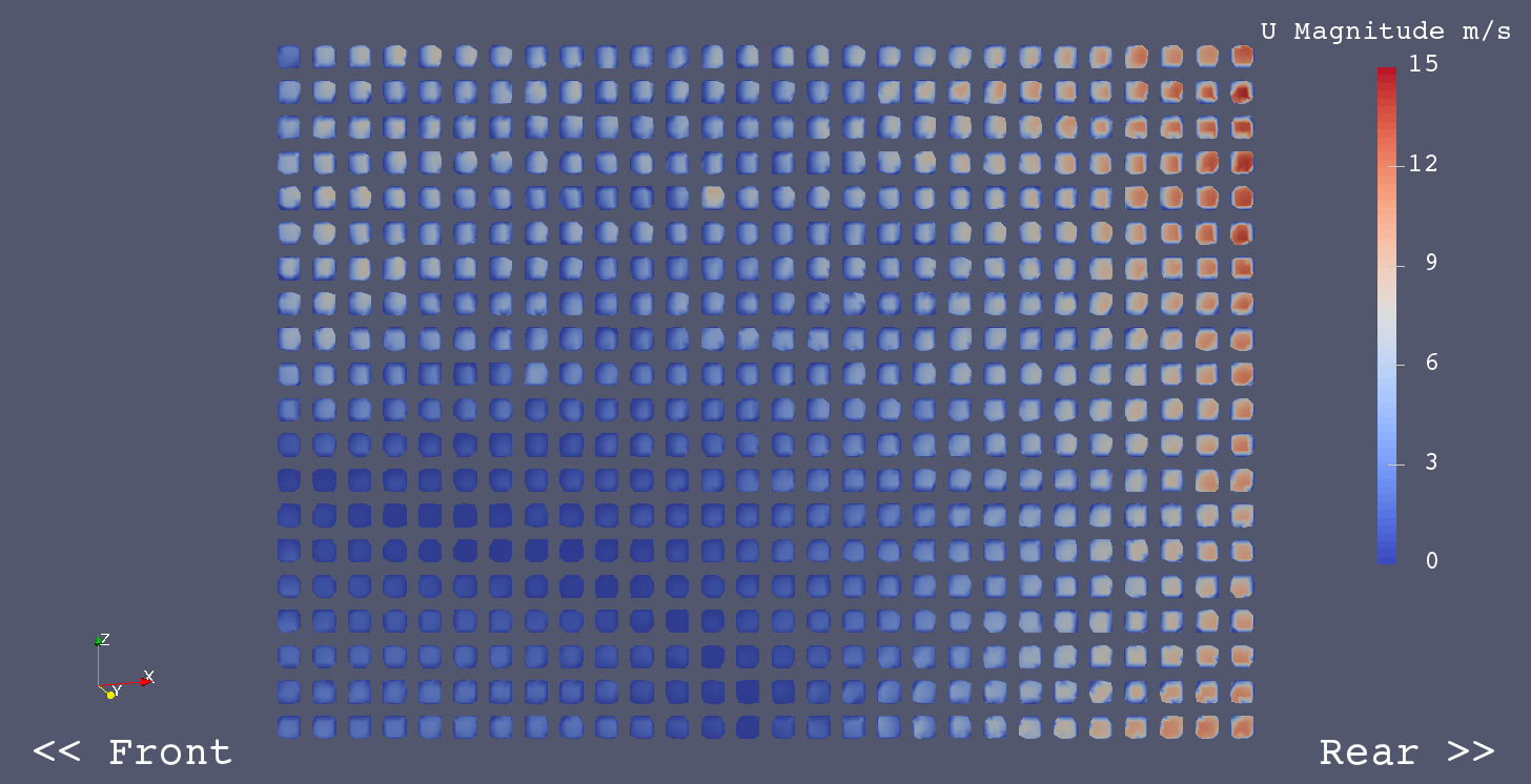
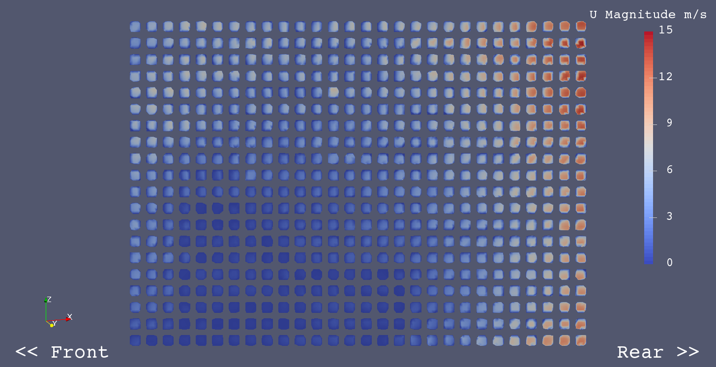
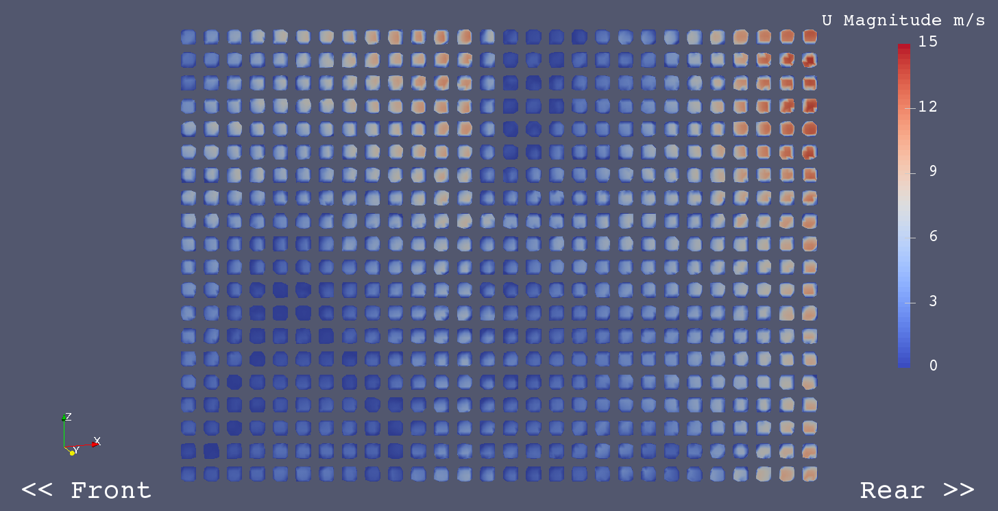
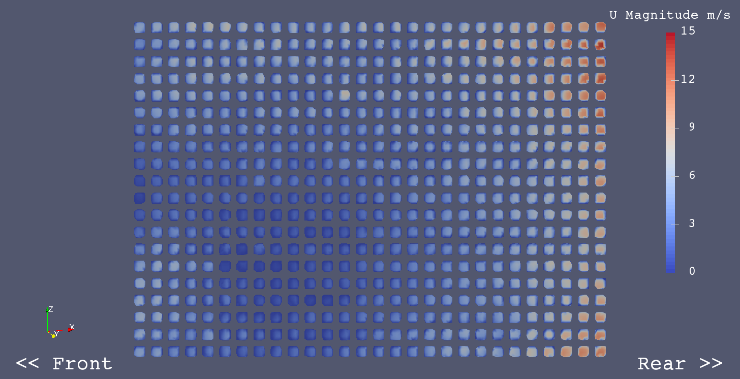
Raditator Flow - U Magnitude
Sidepod Origin - No Radiator
Sidepod Origin - Radiator 20mm x 20mm Holes
Sidepod Origin - Radiator 10mm x 10mm Holes
The designs of the sidepod and the radiator duct were modified for some reasons as followings.
Differences of Sidepod C & Radiator Duct C from the origin
Coefficients of Forces on Body and Wheels
| Coef. | Control | Sidepod C | Difference | Difference % | Remarks |
|---|---|---|---|---|---|
| Cm | 0.0356 | 0.0334 | -0.0022 | -6.2 | |
| Cd | 0.5638 | 0.5632 | -0.0006 | -0.1 | |
| Cl | -0.1806 | -0.1770 | 0.0036 | -2.0 | |
| Clf | -0.0547 | -0.0551 | -0.0004 | 0.8 | |
| Clr | -0.1259 | -0.1219 | 0.0040 | -3.2 | |
| CoP | 0.6973 | 0.6888 | -0.0085 | -0.8 | |
| L/D | -0.3203 | -0.3143 | 0.0060 | -1.9 | |
| RF | 0.1357 | 0.1551 | 0.0194 | 14.3 | Radiator Flow m3/s |
Coefficients of Forces on Body Only (without Wheels)
| Coef. | Control | Sidepod C | Difference | Difference % | Remarks |
|---|---|---|---|---|---|
| Cm | 0.0104 | 0.0080 | -0.0024 | -22.8 | |
| Cd | 0.4548 | 0.4537 | -0.0011 | -0.2 | |
| Cl | -0.2188 | -0.2151 | 0.0036 | -1.7 | |
| Clf | -0.0990 | -0.0995 | -0.0006 | 0.6 | |
| Clr | -0.1198 | -0.1156 | 0.0042 | -3.5 | |
| CoP | 0.5476 | 0.5374 | -0.0103 | -1.0 | |
| L/D | -0.4811 | -0.4742 | 0.0069 | -1.4 |
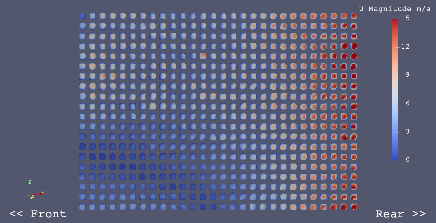
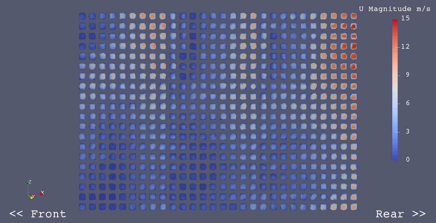
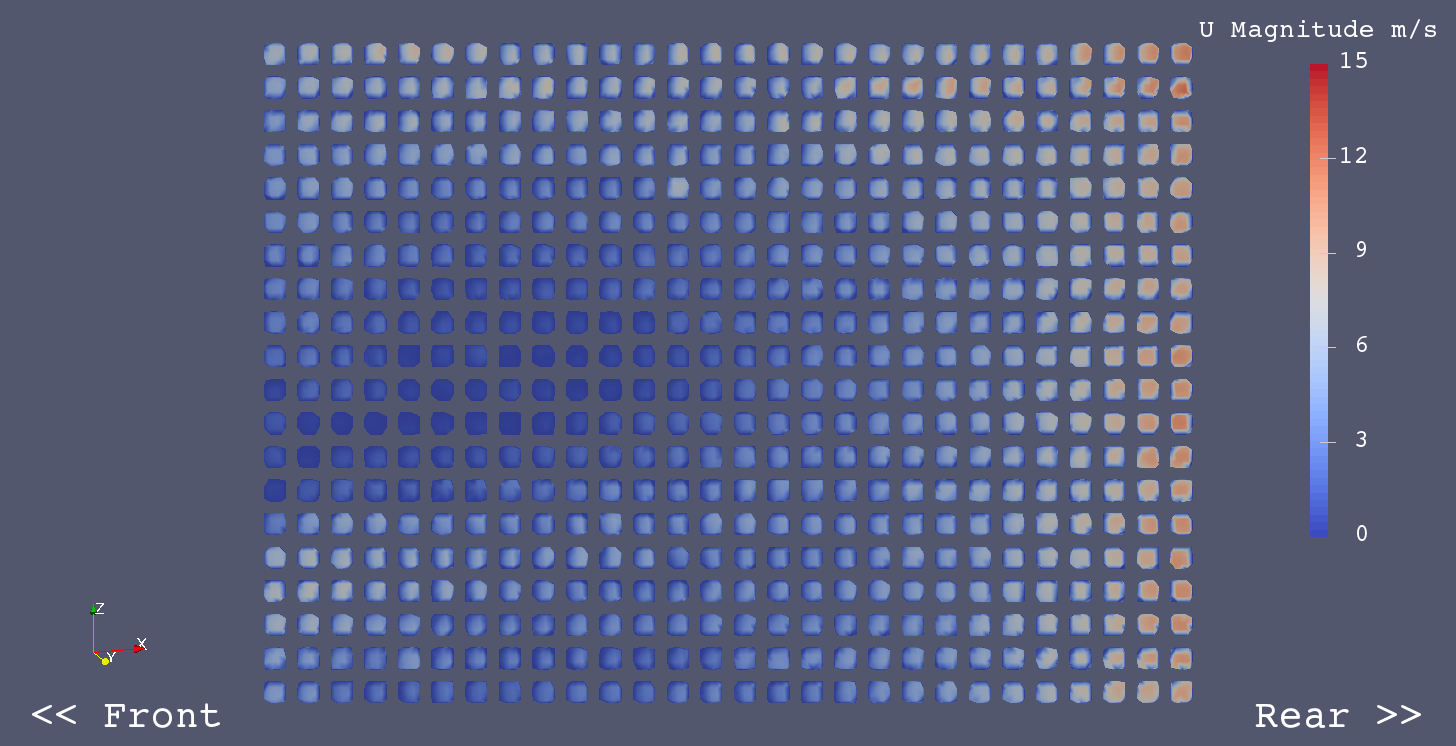
Radiator Flow - U Magnitude
Sidepod Origin - Radiator 10mm x 10mm Holes
Sidepod C
In order to increase the radiator flow, I tried several outlets on Sidepod C.
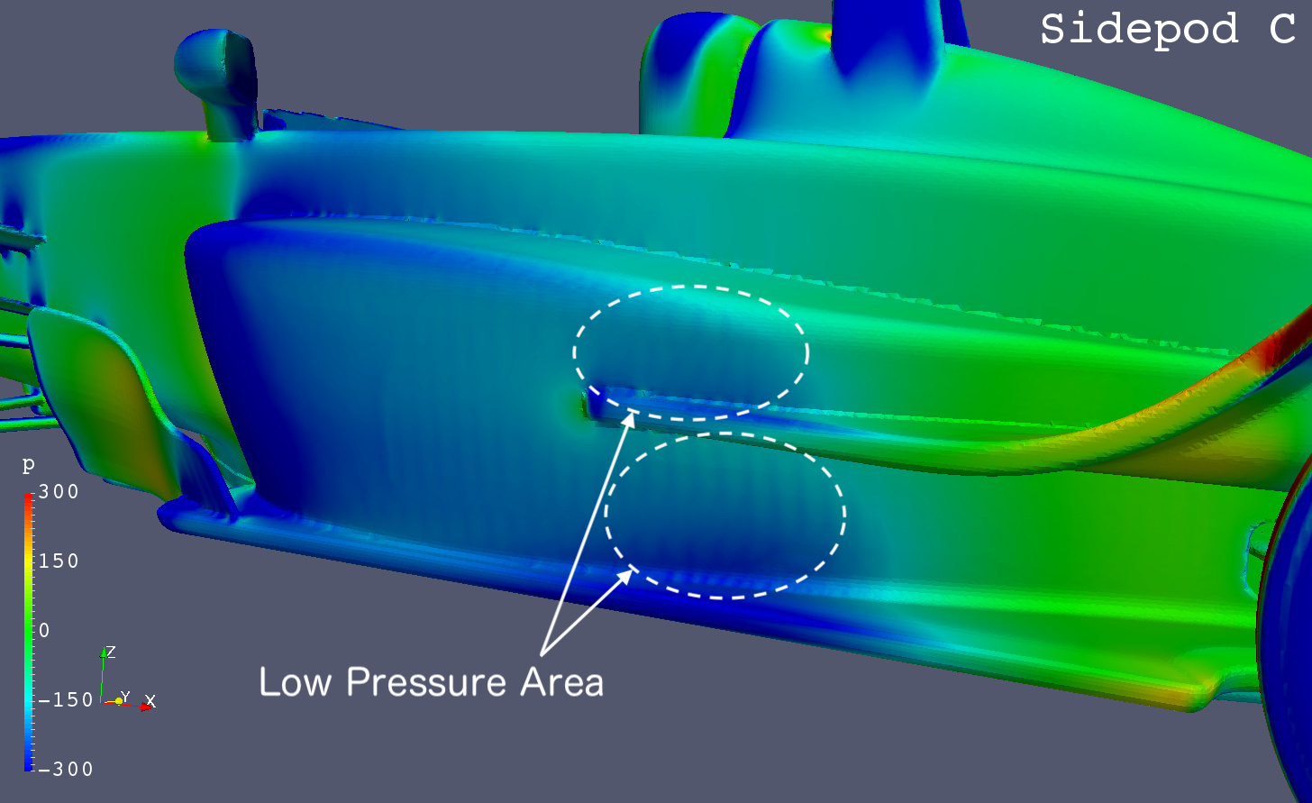
Some low pressure areas are found on the side wall of Sidepod C aft of the radiator as below.
Sidepod C - Pressure / Left View
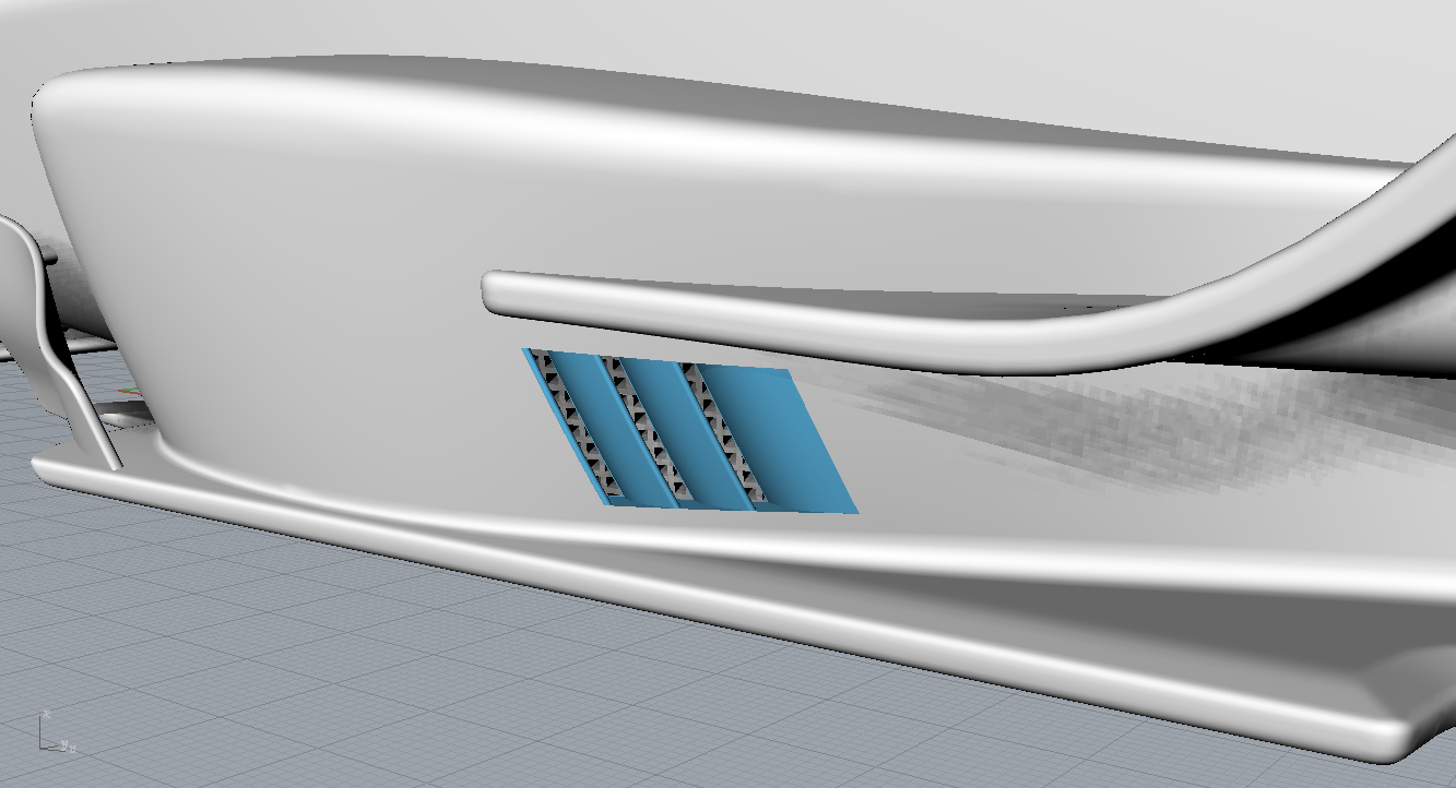
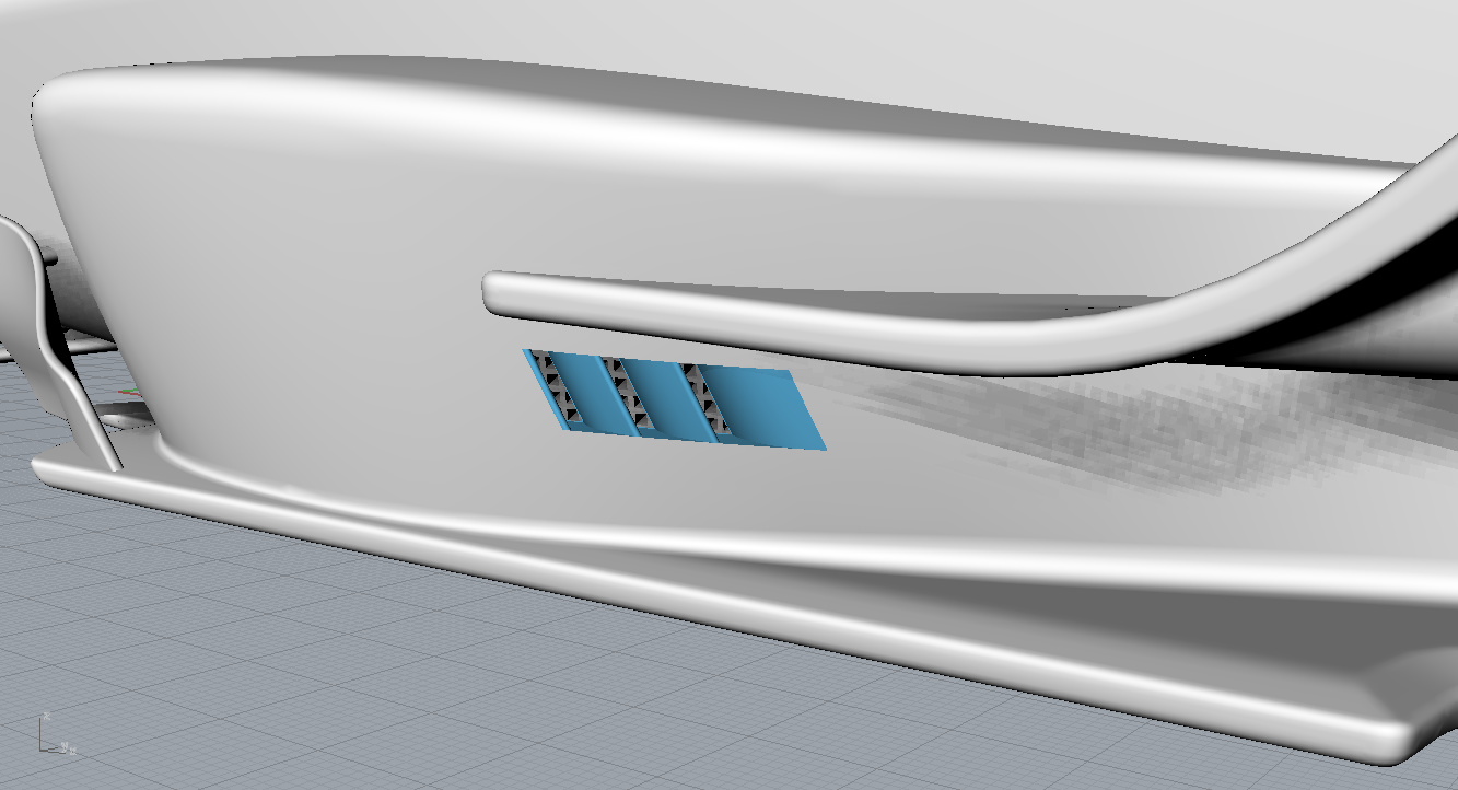
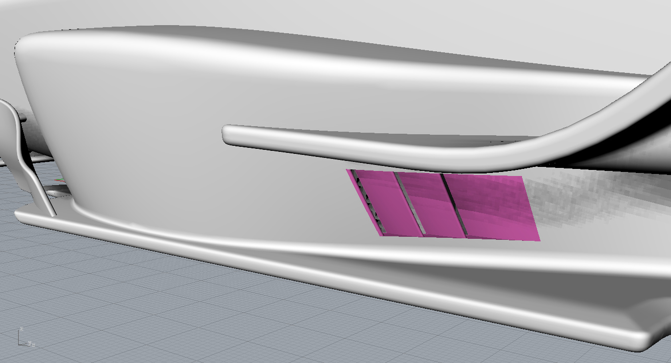
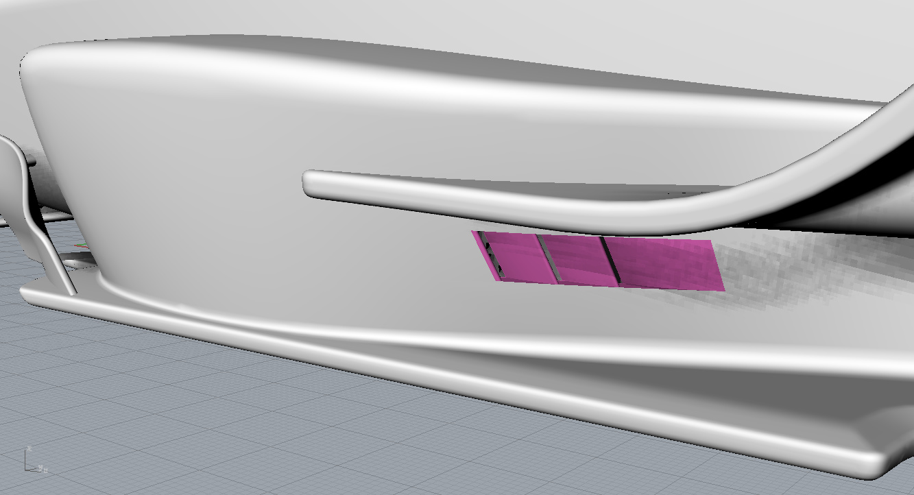
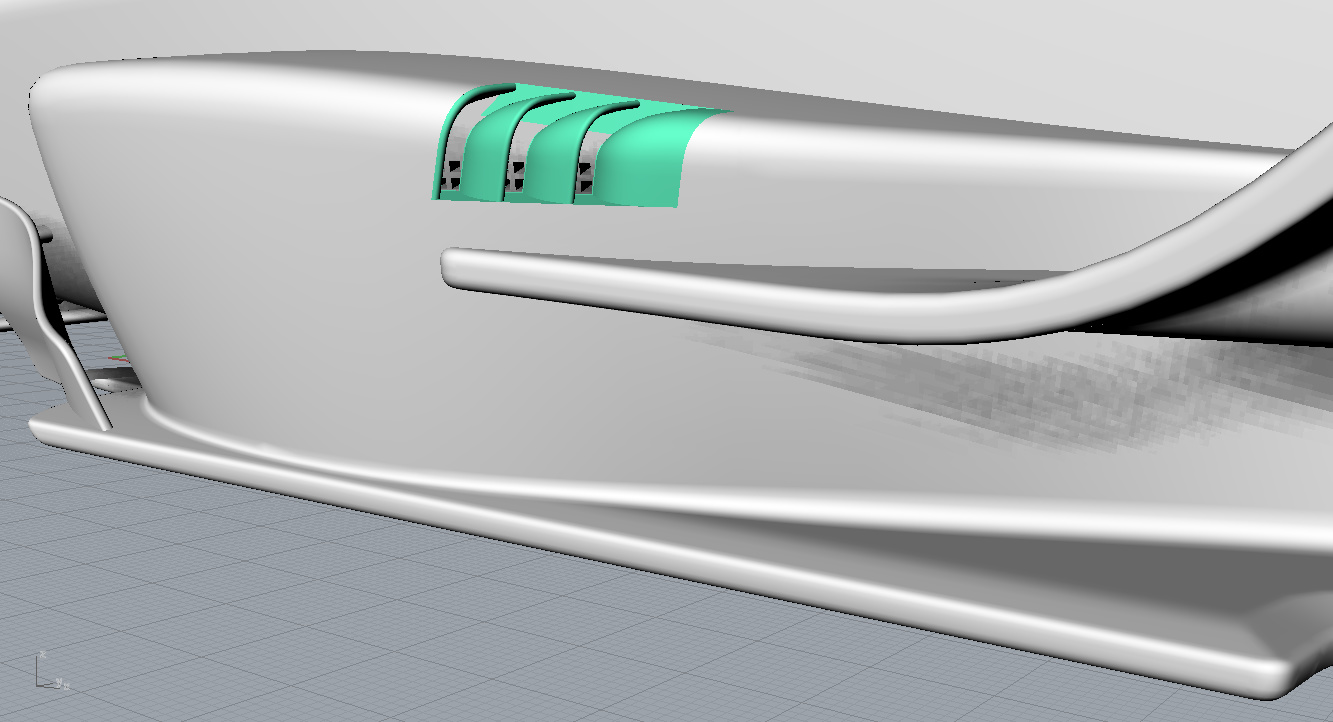
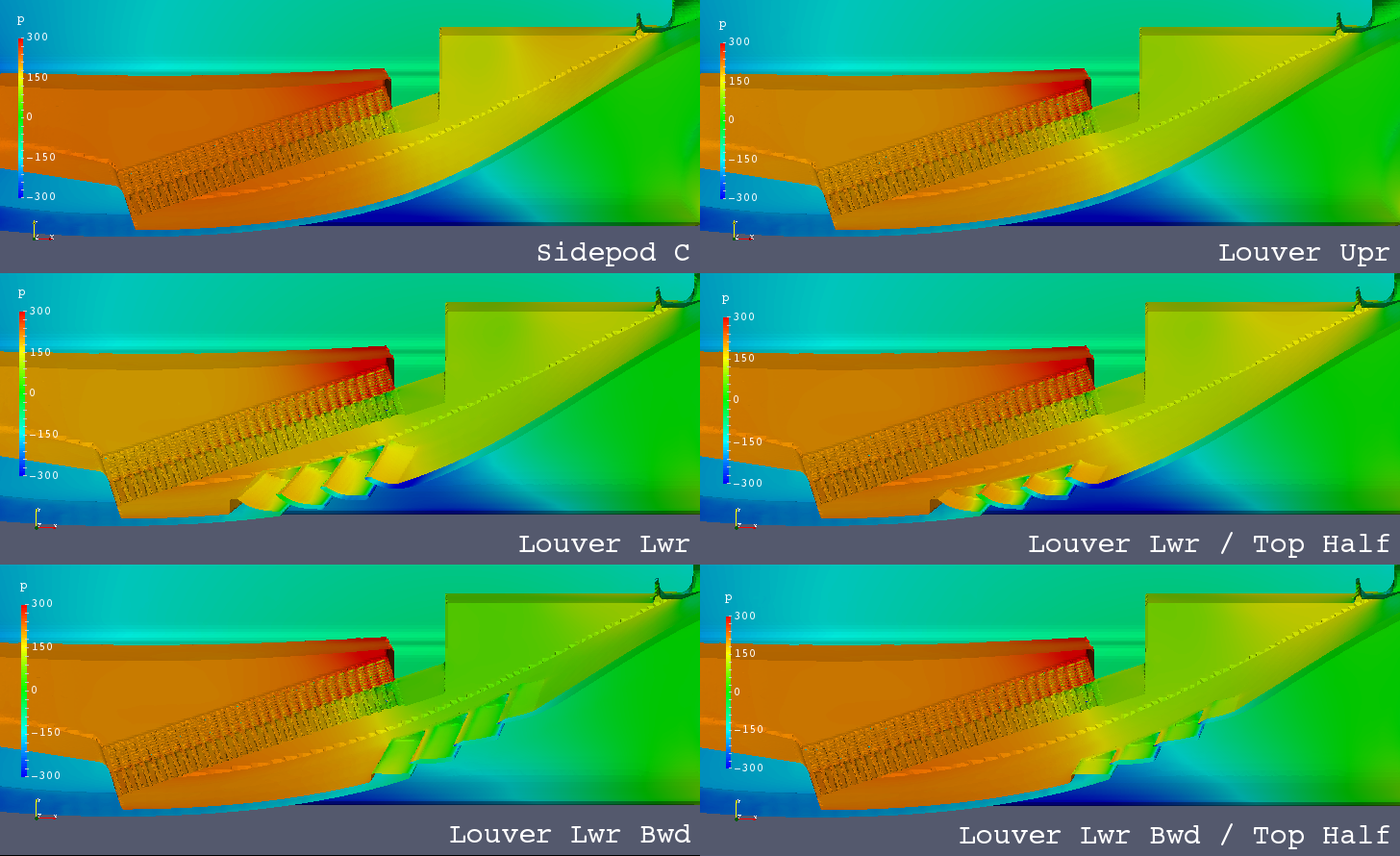
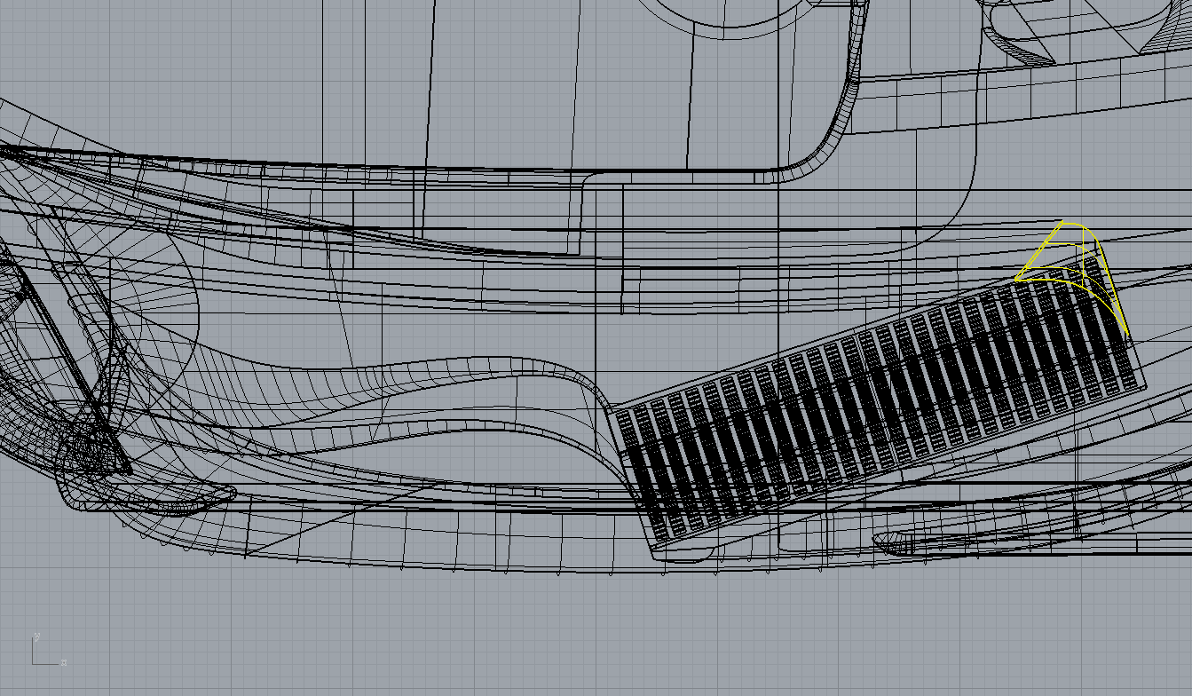
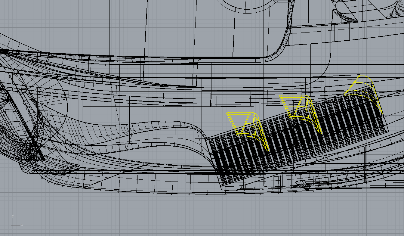
5 outlet louvers on the side wall were designed as followings.
Sidepod C - Louver Lower
Sidepod C - Louver Lower / Top Half
Sidepod C - Louver Lower Backward
Sidepod C - Louver Lower Backward / Top Half
Sidepod C - Louver Upper
Coefficients of Forces on Body and Wheels
| Coef. | Sidepod C | Louver Lwr | Louver Lwr / Top Half | Louver Lwr Bwd | Louver Lwr Bwd / Top Half | Louver Upr | Remarks |
|---|---|---|---|---|---|---|---|
| Cm | 0.0334 | 0.0322 | 0.0329 | 0.0312 | 0.0321 | 0.0311 | |
| Cd | 0.5632 | 0.5636 | 0.5631 | 0.5628 | 0.5628 | 0.5637 | |
| Cl | -0.1770 | -0.1702 | -0.1745 | -0.1673 | -0.1727 | -0.1696 | |
| Clf | -0.0551 | -0.0529 | -0.0544 | -0.0524 | -0.0542 | -0.0537 | |
| Clr | -0.1219 | -0.1173 | -0.1201 | -0.1149 | -0.1185 | -0.1159 | |
| CoP | 0.6888 | 0.6891 | 0.6883 | 0.6867 | 0.6860 | 0.6835 | |
| L/D | -0.3143 | -0.3019 | -0.3098 | -0.2972 | -0.3069 | -0.3008 | |
| RF | 0.1551 | 0.2319 | 0.1939 | 0.2056 | 0.1857 | 0.2133 | Radiator Flow m3/s |
| RF | 1.0000 | 1.4955 | 1.2505 | 1.3259 | 1.1979 | 1.3756 | RF / Control |
Coefficients of Forces on Body Only (without Wheels)
| Coef. | Sidepod C | Louver Lwr | Louver Lwr / Top Half | Louver Lwr Bwd | Louver Lwr Bwd / Top Half | Louver Upr | Remarks |
|---|---|---|---|---|---|---|---|
| Cm | 0.0080 | 0.0069 | 0.0075 | 0.0060 | 0.0069 | 0.0059 | |
| Cd | 0.4537 | 0.4557 | 0.4542 | 0.4550 | 0.4541 | 0.4555 | |
| Cl | -0.2151 | -0.2083 | -0.2126 | -0.2053 | -0.2109 | -0.2077 | |
| Clf | -0.0995 | -0.0973 | -0.0988 | -0.0967 | -0.0986 | -0.0980 | |
| Clr | -0.1156 | -0.1110 | -0.1138 | -0.1086 | -0.1123 | -0.1097 | |
| CoP | 0.5374 | 0.5330 | 0.5354 | 0.5291 | 0.5326 | 0.5282 | |
| L/D | -0.4742 | -0.4570 | -0.4681 | -0.4512 | -0.4644 | -0.4559 |
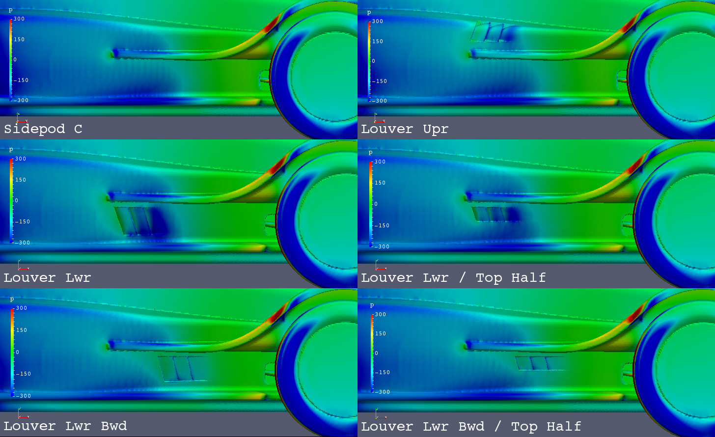
Sidepod C - Louvers / Pressure - Left View
Sidepod C - Louvers / Pressure - Sectional Top View
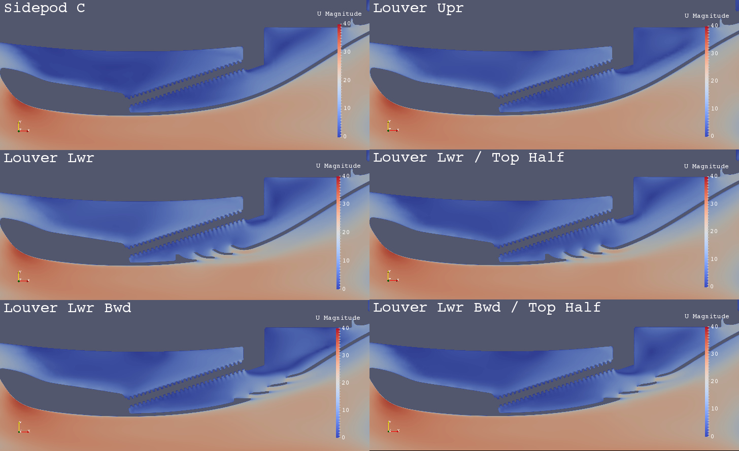
Sidepod C - Louvers / U Magnitude at Z=220mm
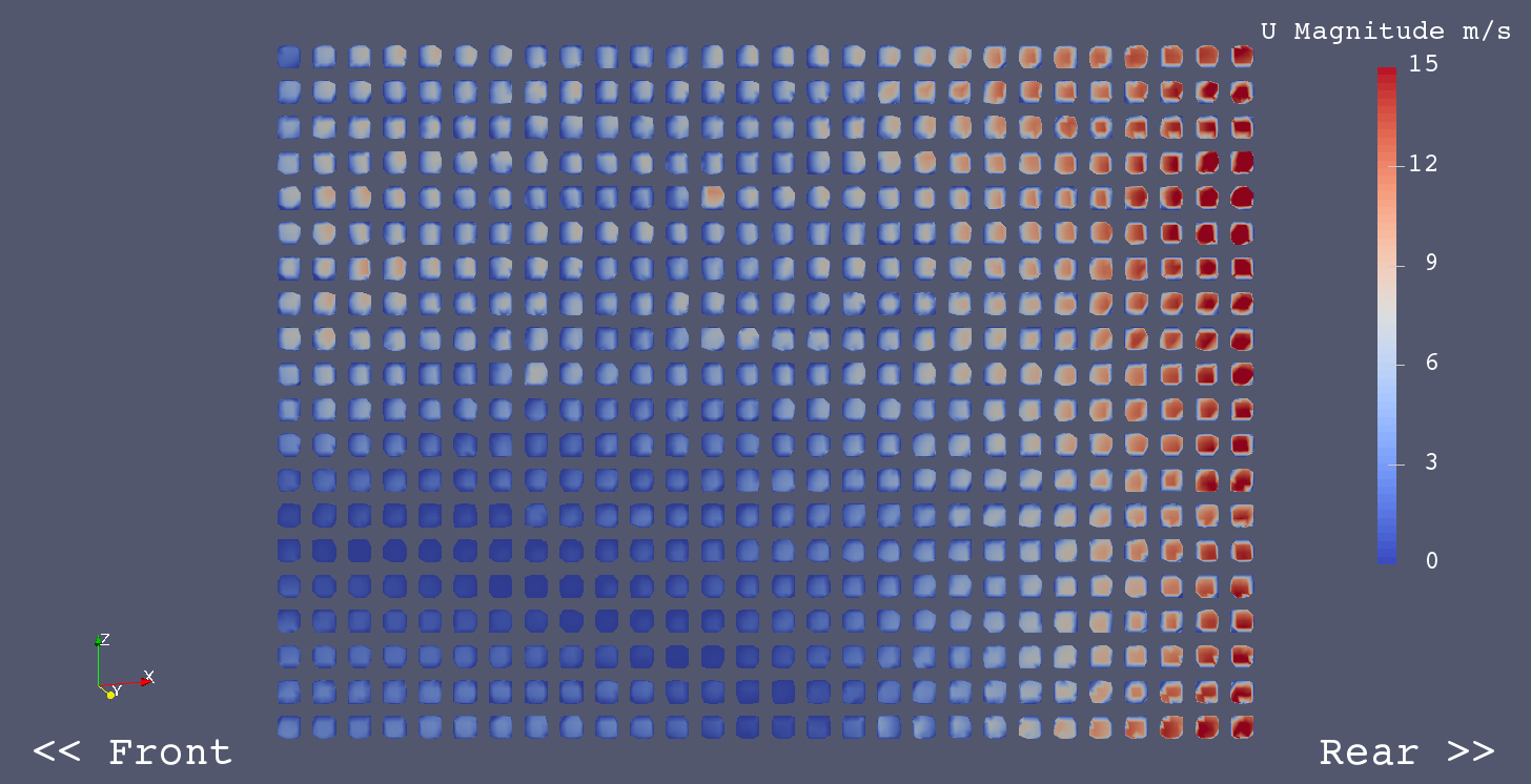
Radiator Flow - U Magnitude
Sidepod C
Sidepod C - Louver Lwr
Sidepod C - Louver Lwr / Top Half
Sidepod C - Louver Lwr Bwd
Sidepod C - Louver Lwr Bwd / Top Half
Sidepod C - Louver Upr
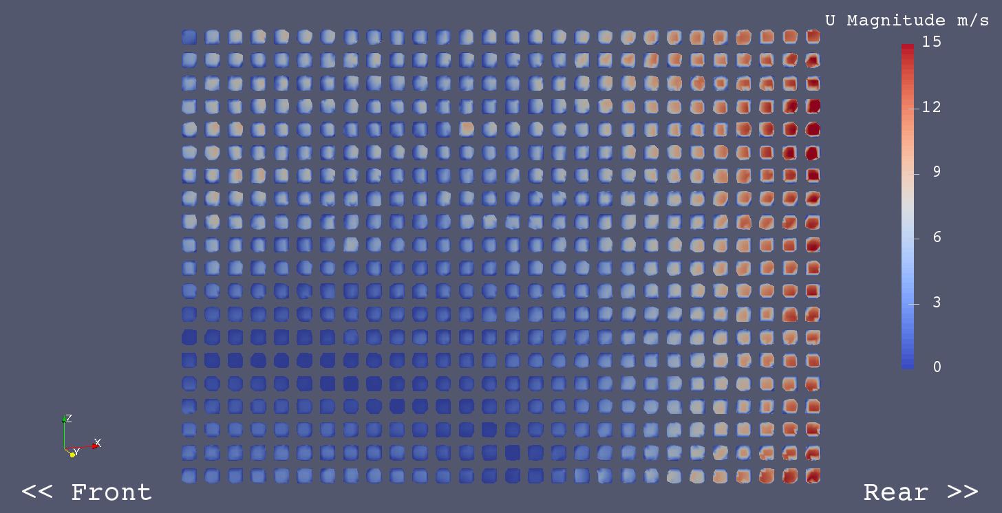
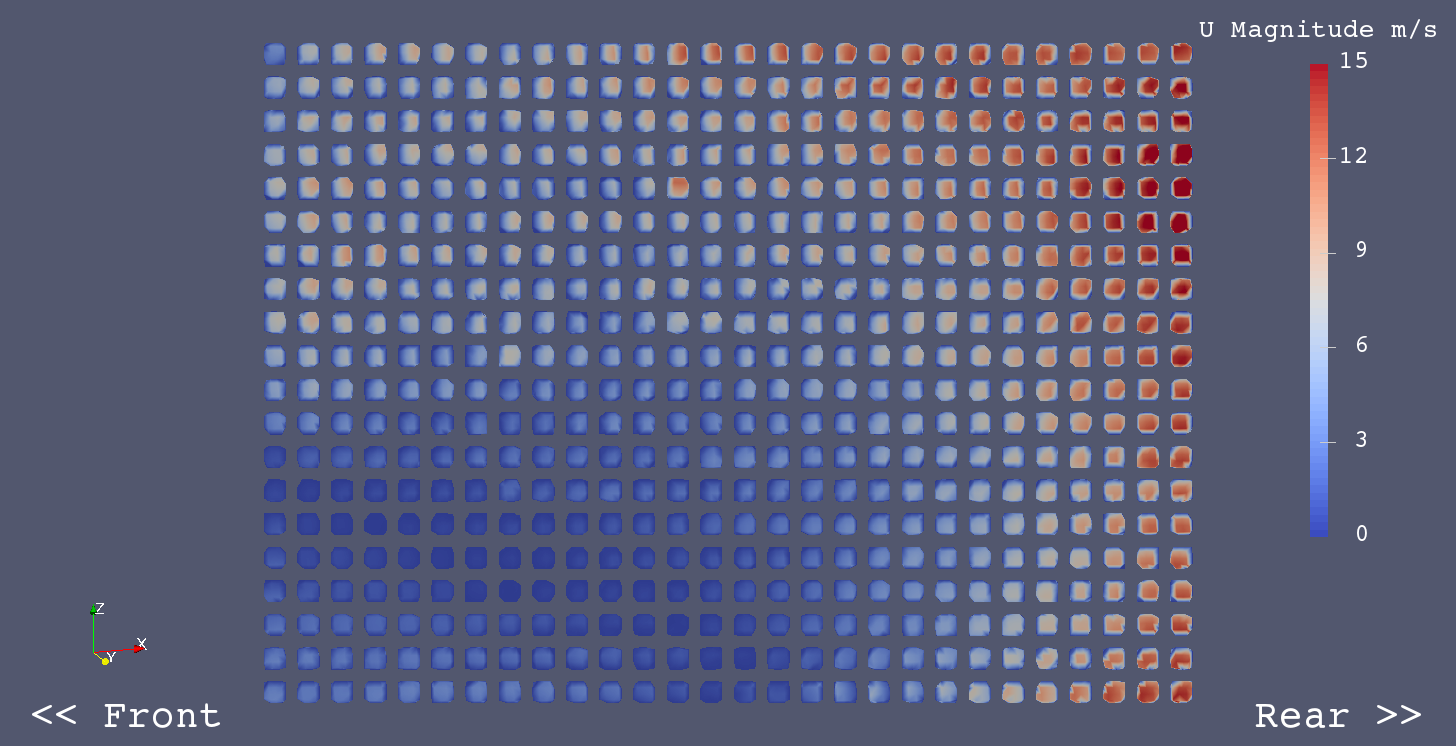
Radiator Duct D was tested for improving the distribution of the radiator flow.
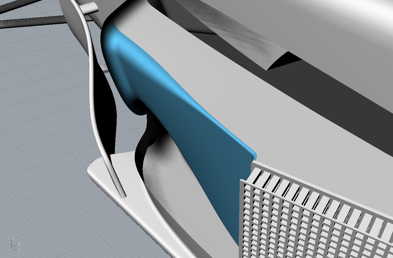
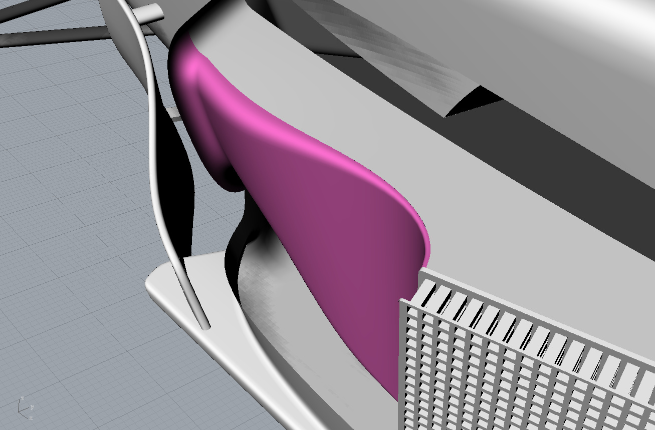
A shape of radiator duct outer wall is modified to a curving shape in “Radiator Duct D” as shown below.
Radiator Duct C
Radiator Duct D
Coefficients of Forces on Body and Wheels
| Coef. | Duct C | Duct D | Difference | Difference % | Remarks |
|---|---|---|---|---|---|
| Cm | 0.0334 | 0.0334 | 0.0000 | -0.1 | |
| Cd | 0.5632 | 0.5634 | 0.0002 | 0.0 | |
| Cl | -0.1770 | -0.1770 | 0.0001 | 0.0 | |
| Clf | -0.0551 | -0.0551 | 0.0000 | 0.0 | |
| Clr | -0.1219 | -0.1219 | 0.0001 | -0.1 | |
| CoP | 0.6888 | 0.6886 | -0.0002 | 0.0 | |
| L/D | -0.3143 | -0.3141 | 0.0002 | -0.1 | |
| RF | 0.1551 | 0.1572 | 0.0021 | 1.4 | Radiator Flow m3/s |
Coefficients of Forces on Body Only (without Wheels)
| Coef. | Duct C | Duct D | Difference | Difference % | Remarks |
|---|---|---|---|---|---|
| Cm | 0.0080 | 0.0080 | -0.0001 | -1.0 | |
| Cd | 0.4537 | 0.4539 | 0.0002 | 0.0 | |
| Cl | -0.2151 | -0.2149 | 0.0002 | -0.1 | |
| Clf | -0.0995 | -0.0995 | 0.0000 | 0.0 | |
| Clr | -0.1156 | -0.1154 | 0.0002 | -0.2 | |
| CoP | 0.5374 | 0.5371 | -0.0003 | 0.0 | |
| L/D | -0.4742 | -0.4735 | 0.0007 | -0.1 |
Radiator Flow - U Magnitude
Sidepod C - Radiatro Duct C
Sidepod C - Radiator Duct D
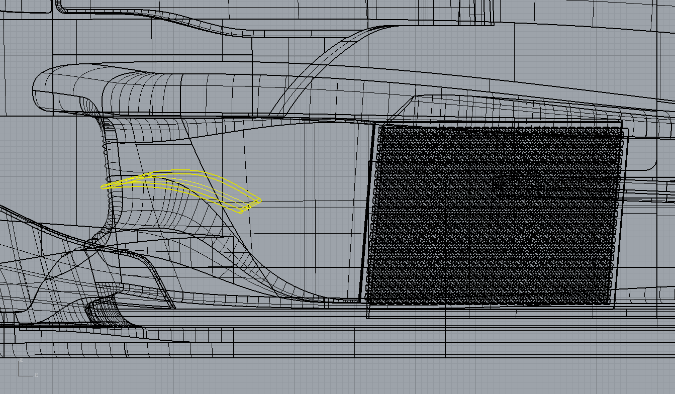
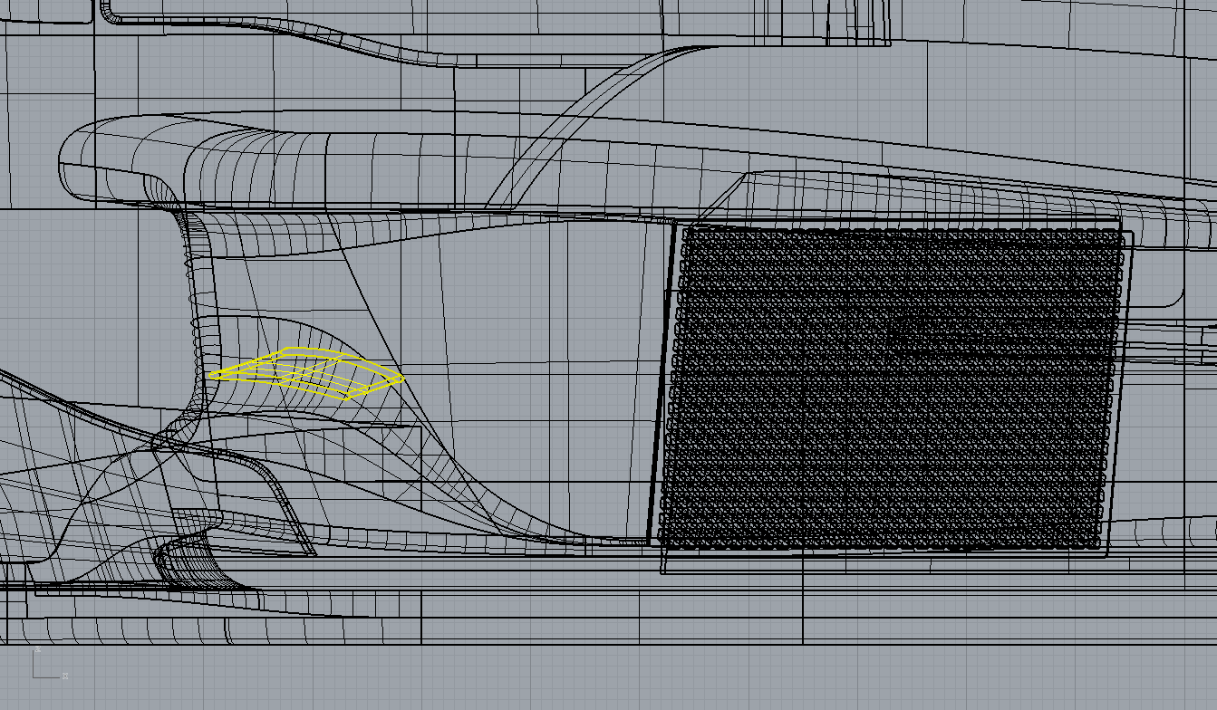
Radiator Duct Turning Vanes were tested for improving the distribution of Radiator Flow.
Vertical Fillet
Turning Vane - Vertical
Turning Vane - Vertical 2 pcs
Turning Vane - Horizontal
Turning Vane - Horizontal B
Coefficients of Forces on Body and Wheels
| Coef. | Control | V Fillet | V 1pc | V 2pcs | H | H-B | Remarks |
|---|---|---|---|---|---|---|---|
| Cm | 0.0334 | 0.0333 | 0.0332 | 0.0333 | 0.0332 | 0.0330 | |
| Cd | 0.5634 | 0.5624 | 0.5633 | 0.5631 | 0.5630 | 0.5625 | |
| Cl | -0.1770 | -0.1771 | -0.1767 | -0.1768 | -0.1762 | -0.1756 | |
| Clf | -0.0551 | -0.0552 | -0.0551 | -0.0552 | -0.0549 | -0.0548 | |
| Clr | -0.1219 | -0.1218 | -0.1216 | -0.1217 | -0.1213 | -0.1208 | |
| CoP | 0.6886 | 0.6880 | 0.6879 | 0.6881 | 0.6886 | 0.6878 | |
| L/D | -0.3141 | -0.3148 | -0.3137 | -0.3140 | -0.3129 | -0.3122 | |
| RF | 0.1572 | 0.1566 | 0.1589 | 0.1591 | 0.1602 | 0.1616 | Radiator Flow m3/s |
| RF | 1.0000 | 0.9967 | 1.0111 | 1.0120 | 1.0192 | 1.0285 | RF / Control |
Coefficients of Forces on Body Only (without Wheels)
| Coef. | Control | V Fillet | V 1pc | V 2pcs | H | H-B | Remarks |
|---|---|---|---|---|---|---|---|
| Cm | 0.0080 | 0.0079 | 0.0077 | 0.0078 | 0.0078 | 0.0075 | |
| Cd | 0.4539 | 0.4529 | 0.4538 | 0.4536 | 0.4534 | 0.4530 | |
| Cl | -0.2149 | -0.2150 | -0.2145 | -0.2147 | -0.2142 | -0.2135 | |
| Clf | -0.0995 | -0.0996 | -0.0995 | -0.0995 | -0.0993 | -0.0992 | |
| Clr | -0.1154 | -0.1154 | -0.1150 | -0.1152 | -0.1149 | -0.1143 | |
| CoP | 0.5371 | 0.5366 | 0.5360 | 0.5364 | 0.5363 | 0.5352 | |
| L/D | -0.4735 | -0.4748 | -0.4728 | -0.4734 | -0.4725 | -0.4713 |
Radiator Flow - U Magnitude
Sidepod C - Radiator Duct D
Sidepod C - Radiator Duct D / Vertical Turning Fillet
Sidepod C - Radiator Duct D / Turning Vane - Vertical
Sidepod C - Radiator Duct D / Turning Vane - Vertical 2pcs
Sidepod C - Radiator Duct D / Turning Vane - Horizontal
Sidepod C - Radiator Duct D / Turning Vane - Horizontal B