Hi all,
After having read many topics about FS car simulations and having followed the related webinars, I still cannot find the solutions to the problems that I am facing. Apologies in advance if these kind of issues have already been solved.
-
A description of the project: FS car full simulation, without MRF neither porous zones.
-
Project link: SimScale
-
A description of what is happening:
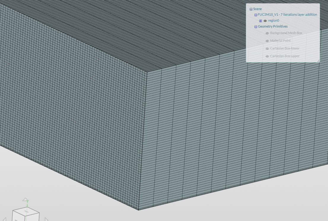
-Firstly, the result for the mesh is not ok (mesh ‘FUC3M18_V1’). The setup indicated in last year webinars has been followed (adapted to our specific CAD), but the resulting mesh features too many illegal cells. Since I realized (I am pretty sure about it, though not 100 %) that these illegal cells appeared due to the surface refinements, I tried the following alternatives:
- Increasing the number of max. iterations for layer addition from 3 to 5 (mesh ‘FUC3M18_V1 - 5 iterations layer addition’): this seemed to reduce the number of illegal cells from > 8000 to ~ 2000. As a consequence, I am now trying to get a mesh with 7 max. iterations for layer addition, which I suppose will yield a lower number of cells. But I do not know neither when it will be enough (i.e. which number of illegal cells can be considered to be low enough), nor whether this is the reason why simulations fail.
- Repeating the same mesh, but with a lower surface refinement (mesh ‘FUC3M18_V1 - Less layer (2, 1.1)’) / without surface refinement (mesh ‘FUC3M18_V1 - No layer car’): in these cases, the number of illegal cells just rocketed!!! (?)
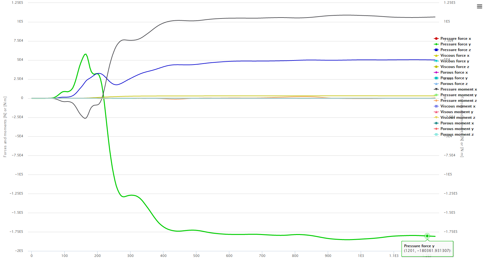
-Simulations were then performed for the meshes ‘FUC3M18_V1’ (the original one, 8000 illegal cells) and ‘FUC3M18_V1 - 5 iterations layer addition’ (2000 illegal cells). In both cases, the simulation just diverged massively, which led to incoherent results -it can be checked in the results control: forces in the wings and the car-. Just in case it was the reason of the trouble, both simulations were also run without the rotating BC for the wheels, but again the same kind of results were obtained. Note that, when the simulations stopped, a window saying that ‘numerical inestabilities’ may be the cause of our problem appeared. But I do not know how to interpret that information.
To sum up: would it be possible for you to take a look to this meshes / simulations and tell us about what could be the origin of our problems? @anon18194957 @pfernandez Thank you so much, any help will be welcomed.