Hey there.
I got a question perhaps regarding the issue of ground effect influence. I did a simulation on our formula SAE car of 2015 to learn about aerodynamics and their influence. So now I was wondering…
In our old system that we used to use the diffuser had around 100N downforce (for half of the car). In Simscale together with the Sidewings I was wondering to have an outcome of only 28N Downforce for half of the car.
Then I wanted to separate these two components to look out for the downforce loss and I was shocked to watch the diffuser with 40N Lift instead of Downforce and the sidewings got 68N downforce. How’s that possible. It is the same car as in the old system that we originally used but did not want anymore. The difference between more accurate Simscale and the old system was that Simscale uses ground speed and the old one uses wind speed (no moving floor). What has happened here? What could be the cause? Could it be an effect influence like Ground effect?
Has anybody gotten to deal with this problem yet?
I am happy for every hint and answer.
Thanks in advance.
but I paid attention to my last simulation to this point and it didn’t differ alot. I gained downforce at the wings because of this error, but the diffuser stays strange… so I figure these two issues do not match…
The flow around tires and wheels is particularly complicated.
Therefore, generally, the diffuser shape device does not necessary act as a diffuser in that area,
and there are some possibilities it acts as a tire-fairing or other things.
The wing shape is also the same in complicated flow.
It is said that there is likely to be a difference in the calculation between the simulations.
It is ideal to compare just the differences in shape by arranging all the simulators and calculation conditions the same.
But as it is,
did you compare the pressure on body surface and flow of these simulation results?
If you have done it, is it possible to show us screen captures (and so on) comparing them?
Hey @yosukegb4
yeah thats exactly what our team did. we used several different diffuser types and compared them to gain any values at all. but the thing is that each of the diffusers got strangely wrong values. So how can I just conclude that the error is comparable if it does not make sense at all? I guess that would be only jumping to conclusion and that does not help anyone… I can surely tell that our values for the diffusers must be nonsense bc we even sometimes got negative drag for the diffuser and that is just wrong. We tried to look at the surface pressure & streamlines but couldnt see something strange happen… perhaps we did not look close enough but anyway we tried to play with the values. The residuals did look normal and the mesh was okay too (we ran the check and checked the meshing log).
I try to make pictures together with my team and upload them asap. thanks for your help!
Hey @yosukegb4
I placed all the diffusers my team and I tried to simulate in one project.
Sorry that it took us so long. We had exams lately.
now you should be able to look at all the plots and values and also what the diffusers look like.
normally it should differ somehow in the simulation results. But the negative drag does not make sense and the lift does not either… It does not matter whether we put the diffusers with the car in there or alone… We did those tests to gather any kind of values. But we didn’t gain any senseful results. Fun fact is that we even did some with vertical plates on top to look whether the plates get senseful values and they did. But the diffusers did not no matter what we tried.
Do you have any explanation for this? We ran out of ideas. Thanks for your help.
I saw the solver log of your simulation UB15.
It seems fine.
Cd = 0.0430753655941 means the drag is occurring. Cl = -0.194561900643 means negative lift = downforce.
Cl(f) = -0.0972809503214 and Cl(r) = -0.0972809503214 mean nothing, just the half of Cl.
Because you did not set “Pitch axis” in the simulation control and the simulator could not calculate Cm.
Are you mentioning about other simulations than UB15?
Best,
Yosuke
SIMPLE solution converged in 960 iterations
forces forces10 output:
    sum of forces:
        pressure : (4.97442048777 1.5383757528 -25.4228245836)
        viscous  : (0.64238663982 -0.000541138910881 0.0529488967281)
        porous   : (0 0 0)
    sum of moments:
        pressure : (4.39586457807 22.7437987877 2.44444689798)
        viscous  : (-0.00871615660155 -0.0178785594049 0.112023343573)
        porous   : (0 0 0)
forceCoeffs forceCoeffs11 output:
    Cm    = 0
    Cd    = 0.0430753655941
    Cl    = -0.194561900643
    Cl(f) = -0.0972809503214
    Cl(r ) = -0.0972809503214
End
Finalising parallel run
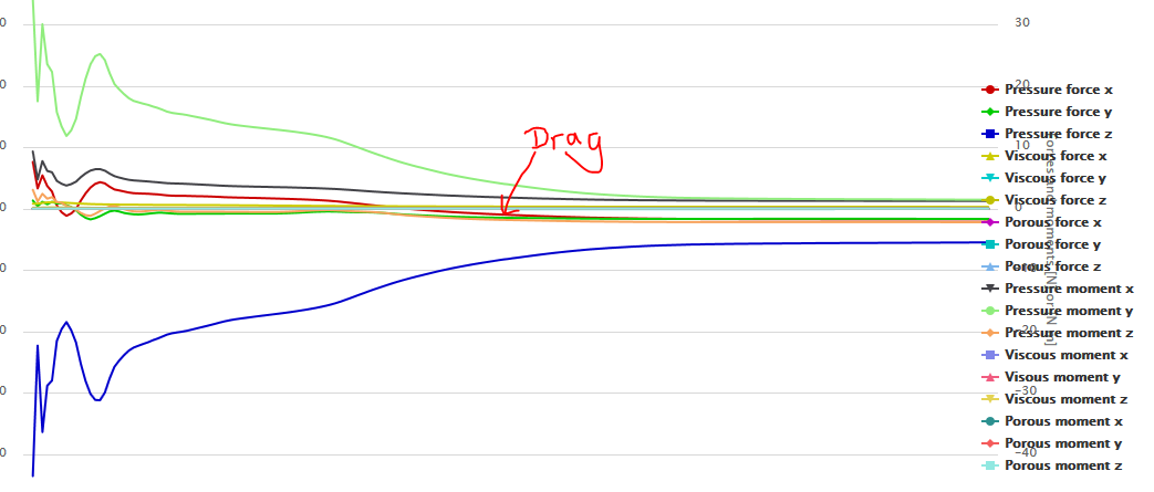
thanks for your answer. yeah the Cl and Cd look normal but the force plots do look strangely. Some of them have pressure force x which should be drag negative and pressure force z which should be lift positive. Thats what I was wondering about. How is that even possible if the Cd and Cl are normal looking.
Just looking at the force plots makes me wonder. Might this only be a minus error? but thanks for rechecking anyway
It is not clear for me that which result you are mentioning about.
Could you tell me the name of simulation that ‘pressure force x’ is negative drag and ‘pressure force y’ is lift?
this is UB20.2 and its drag is negative. So we started wondering. Right after our car undertray diffuser got lift.
what happened here? and why does it evaluate so differently. It’s the same as UB20 except for there is a plate on top to evaluate the results.
As soon as you put in another component it evaluates nonsense for the diffuser. Is that like an interaction between the two? But still it does look really weird, negative drag would be a perpetuum mobile which is not possible. What is the simulation doing?
All the ones completely alone look normal. If you put whatever other component with it in there it makes strange things. I try to get one of the car with separated sidewings and diffuser too, then you’ll see that our diffuser has lift also. I will do this this evening.
Hi @yosukegb4 Thank you very much in advance! We really appreciate it! I will put the simulation of the car with the separated sidewing and diffuser on my dashboard as well so I hope it is the same issue here as it is in UB20.2 greets
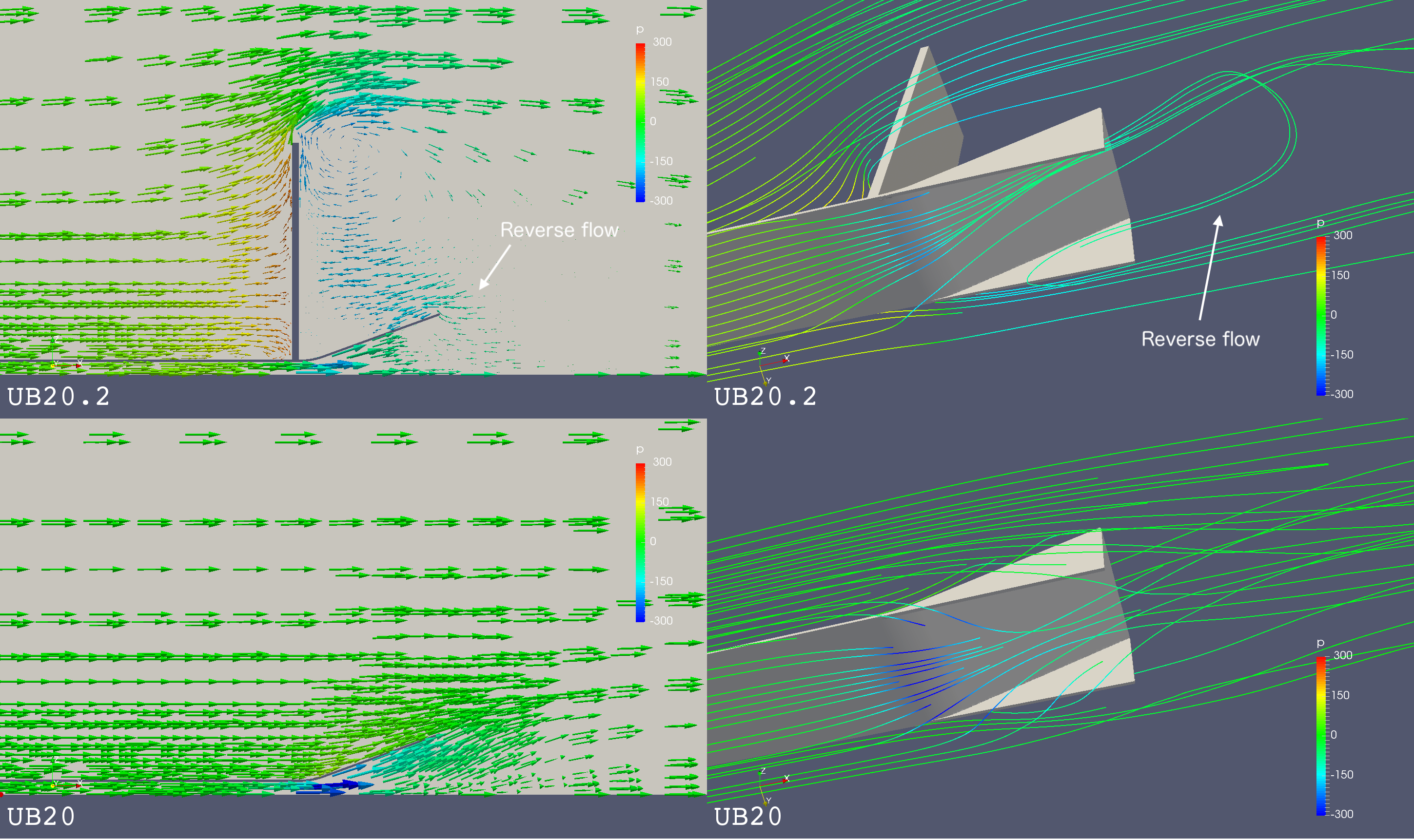
Briefly speaking, ‘Platte’ of UB20.2 disturbs that the diffuser works.
Please see explanations below.
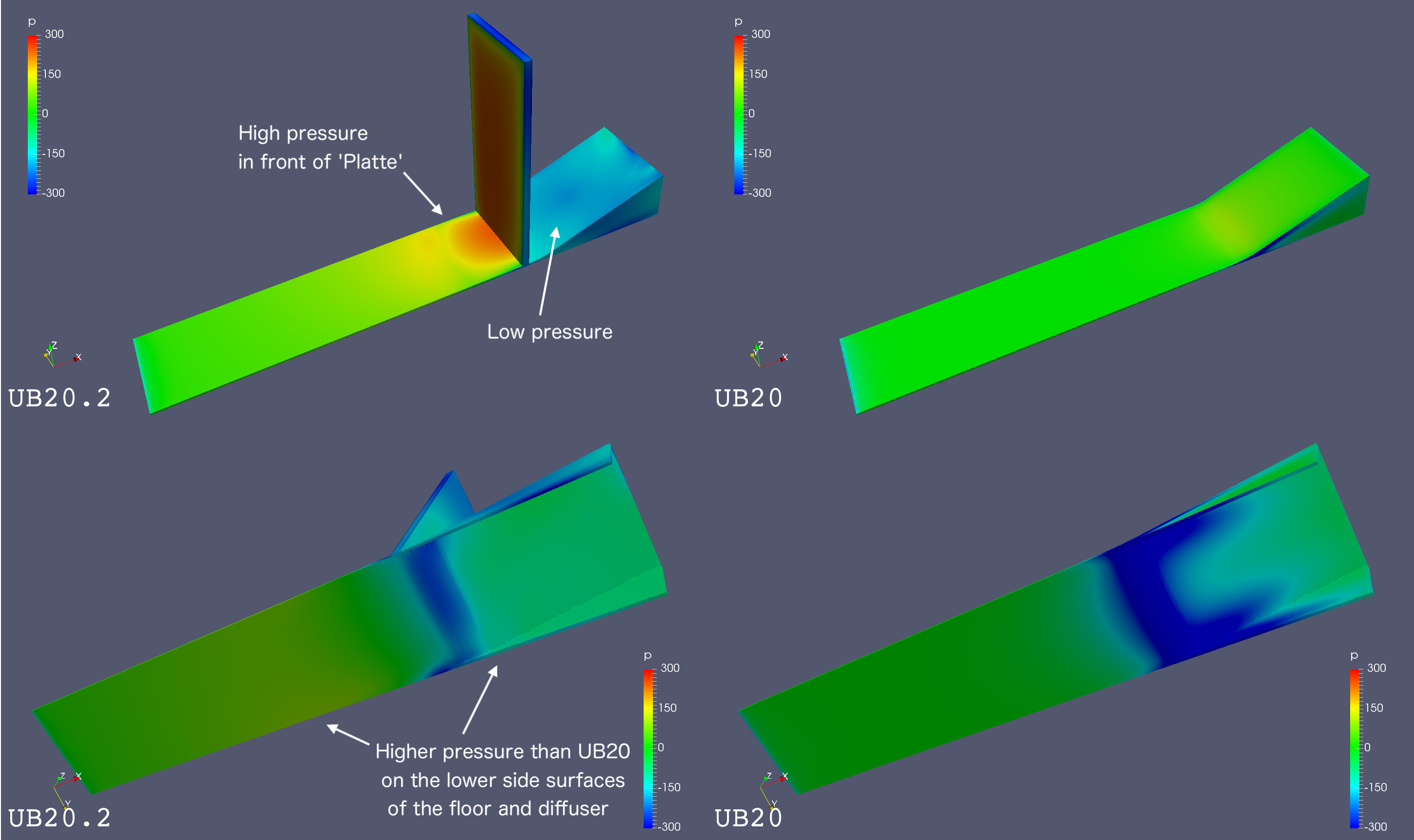
1. Pressure Comparison
I found some features in the pressure result of your simulation UB20.2 comparing with UB20.
Low pressure on the upper side surface of the diffuser
High pressure on the upper side surface of the floor in front of ‘Platte’
Higher pressure on the lower side surfaces of the floor and the diffuser
It seems that the area in front of ‘Platte’ increases some downforce, but the area is not large.
On the other side, the low pressure area of the upper side of the diffuser and the higher pressure area of the lower side of the floor and the diffuser increase lift force. And the areas increasing lift force cover larger.
I think that lift force is generated as the sum of those pressures.
The difference of the pressure between the upper and lower surface of the diffuser UB20.2 also generates negative drag.
yeah they really did help. Could it be the case that the diffuser on the car has the same issue? Like that the sidewings also influence the diffuser as the plate “Platte” did in these single simulations? Or do you think it’s a simulation error?
If it is really the sidewing pulling upward then a diffuser does not help by anything and is useless…
that would explain a lot. thanks for all your effort you already put in this case. I appreciate it very much. ^-^
here it can be seen. look at the simulation “Starkstrom Standard”. this is the correct simulation. perhaps you can see something in the post-processor that I can’t see.
The diffuser is only slightly negative bc the sidewings got downforce. The sidewings alone were simulated by another team member without a diffuser and got -68N. So this means that the diffuser has 40N lift. I could get this simulation as well if it helps… we have no idea why that occurs. thanks already for your efforts!
When you can’t see results on the post-processor of SimScale web page,
you can download result from SimScale and see them on ParaView in your PC.
Please analyze your results on ParaView.
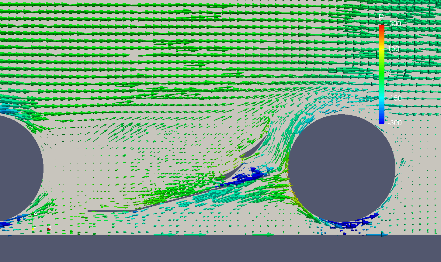
The flow of ‘Starkstrom Standart’ is different from the flow of UB20.2.
But the same point of view is the difference of the pressure between the upper and lower surfaces of the diffuser.
In ‘Starkstrom Standard’ the side wing is too close to the diffuser so that the low pressure generated by the side wing affects on the upper surface of the diffuser and pulls it up.

 perhaps we did not look close enough but anyway we tried to play with the values. The residuals did look normal and the mesh was okay too (we ran the check and checked the meshing log).