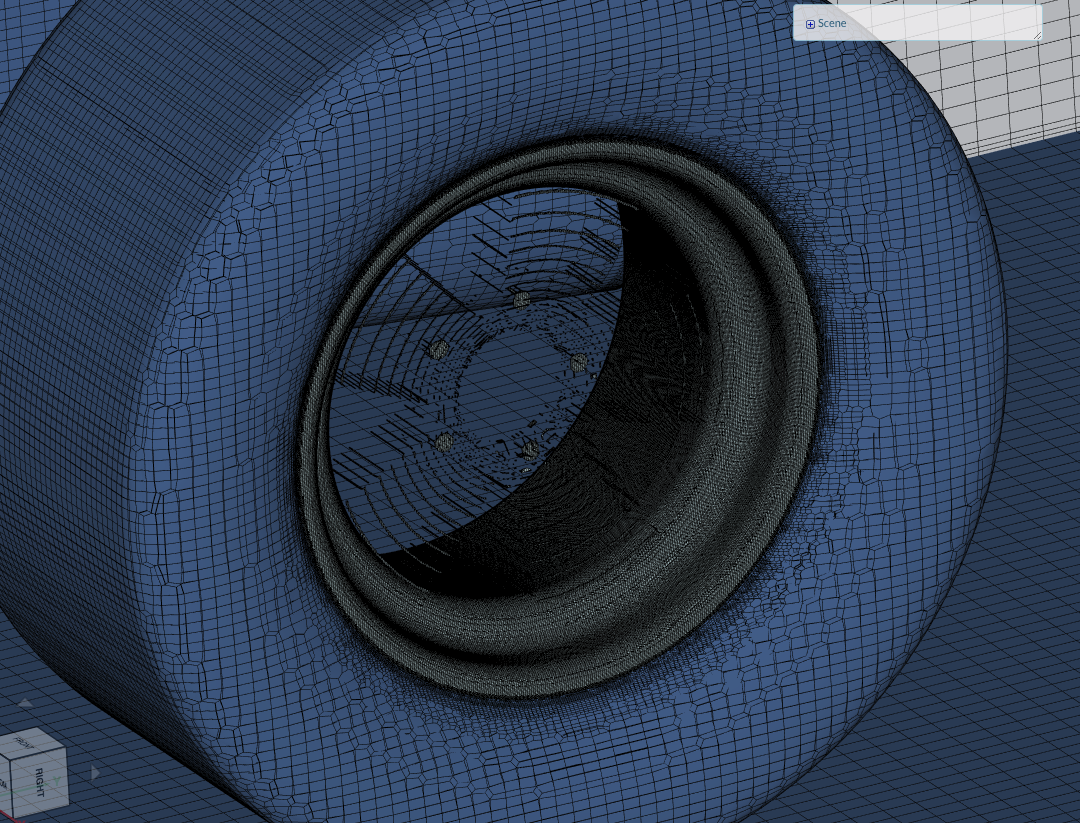
I tried to simulate the effect of the front wheel on the front wing, but I got an error (Floating point exception). Although I have made some of the corrections which are suggested in this post ( Most Popular Errors of Simulation - #3 by jprobst ), the result is still the same. Maybe the problem is my MRF zone which after mashing process looks strange.
Please tell us if you managed to fix the issue. On top of that make sure to set your project to public so that we can have a look at it. The inner structures of the wire look very weird at the first glance - why is that?
Now the project is set to public, so you are able to see it. Setting a rotation axis for MRF was a solution, but the run time was so long (more than two hours), so I decided to stop it. The cause of this long run time is probably the rim (MRF zone), therefore I will simplify the geometry of it. Hopefully this will help.
I spotted that actually the geometry wasn’t closed because the bounding box intersected with the wheel and therefore a hole was made. So I just made bounding box a little bigger, maybe this fill fix the problem.
Issues are still here. After the meshing proccess the meshing log says that my geometry is not closed. So maybe that is the reason altough I cannot see where is the hole.
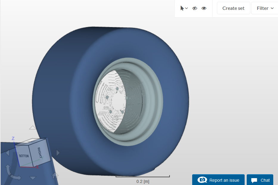
As can be seen in the picture there is something wrong with the tire. Maybe you can simplify the geometry and just try it with a plate and what also is a big issue are the solids that have to be split into different faces! Can you fix this any get back to me as soon as you have finished the pre-processing part? We can do this
I have made a simplified rim and ran a meshing process. After a run I got an error saying that my geometry is not closed and that there are some self-intersections. I do not know where to look at for these irregularities. Maybe the tire, which after the meshing process has some strange shapes?
The best thing is to create a simplified geometry first and test it with that. Which software for CAD model creation are you using at the moment? I think Autodesk and some others have options to check watertightness to make sure things like that don’t even occur in the first place before working on a CFD analysis.
Cleaning up a CAD geometry is always problematic especially when the geometry is very complex. For AutoCAD I’m not sure if there is an automatic repair tool for CAD but for Solidworks there is when you import a model in. Maybe you can try exporting it out from AutoCAD and importing it into Solidworks.
There are plenty of solutions out there so do try some google searching regarding cleaning up CAD geometries.