Dear SimScalers,
in this weeks spotlight we will have a look at a FEA simulation of an Elastoplastic Oil Pipe by our user @hramesh_babu .
Application:
A blowout is the uncontrolled release of oil or Natural gas from an Oil Rig, after pressure control systems have failed which leads in disaster. To prevent this, the pipe needs to be analyzed and Simulations should be carried out at different scenario.
Objective:
Pipes in Oil and Gas Industries are widely exposed to higher temperatures and pressure which might lead to blowouts. To prevent due to blowout, closing and sealing of pipes is of high necessity. For this, the pipes are simulated for Nonlinear Case with larger deflections and contacts using two flat stiff indenters.
Geometry
Format: STEP
The 3D-CAD Model is modeled in Online Software Onshape. The following CAD figure is used for analyzing.
g/tet-dominant.html?highlight=tet%20dominant)**
The dimensions of the Model are as follows:
- Indenters: Width = 200mm, Height = 227mm.
- Pipe: Outer Diameter = 200mm, Inner Diameter = 175mm.
The geometry was meshed using parametrized tetrahedralization.
The mesh is shown below:
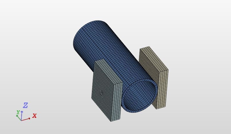
Nodes: 23770
1D elements (edges): 704
2D elements (faces): 7593
3D elements (volumes): 107964
Simulation:
Type: Static Analysis - Advanced
Simulations Details
The Properties of Mesh are as follows:
- Mesh Type: Tet-Dominant
- Element Sizing: Coarse Mesh
- Element Order: First Order
Since the geometry has nonlinear contact behavior coarse mesh is used to reduce the computation time to obtain the results.
Boundary Conditions and Simulations:
The important part of the model is to choose the analysis type and choosing the boundary conditions for the respective CAD Model. Both the indenters have contact with pipe. The Indenters acts as a Master components and Pipe acts as a Slave components.
Numerics
Equation solver: Multfront
Results:
Displacement
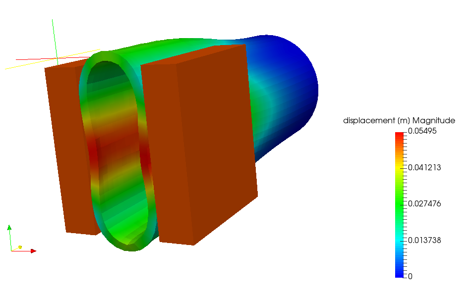
From the above figure it clearly states that, there are larger displacements in the center of the pipe, this is because of contact with two indenters. The two indenters has physical contact with center of the pipe which results in maximum displacement when compare other cross section of the pipe.
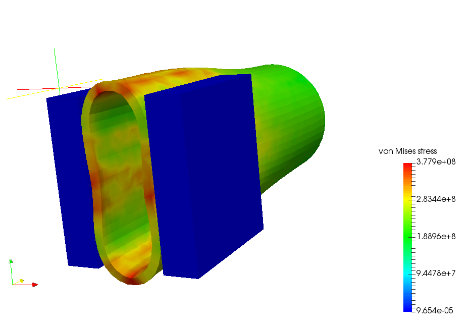
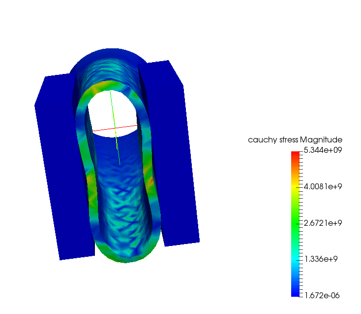
The Von-Mises stress is the equivalent stress of the component (reference configuration), whereas the Cauchy Stress signifies the deformed stress (i.e.) stress obtained in the current configuration according to Continuum Mechanics. The following figures represents Von Mises and Cauchy Stress.
Von Mises Deformed Shape
Cauchy Stress
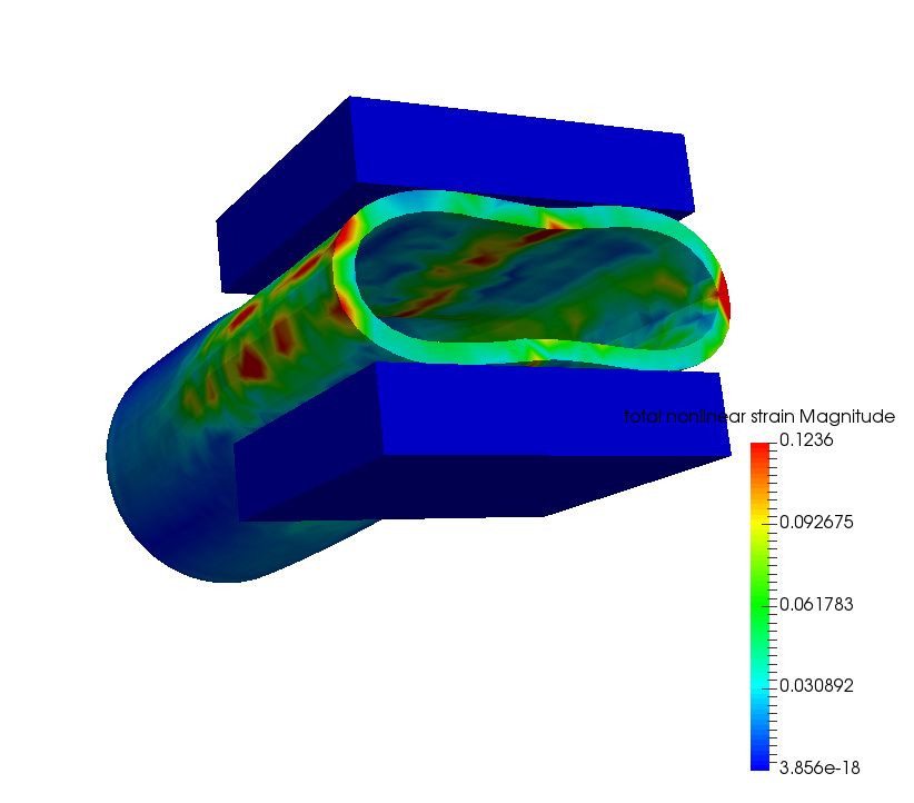
The below mentioned figures refers to the total nonlinear strain in deformed state. One can be able to see that the accumulation of Nonlinear strains in the middle of the pipe because of the physical contact.
SimScale project:
To look at the simulation setup, please have a look at the project from @hramesh_babu :
Elastoplastic Analysis of an Oil Pipe
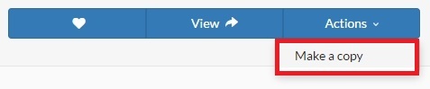
To copy this project into your workspace, simply follow the instruction given in the picture below.
\underline{\textbf{Visit our SimWiki by clicking on the picture}}