I have done a simulation which can be found here: . Please be aware that I added bonded contacts instead of the physical contacts you had before for testing reasons but changing that should be no problem. On top of that I added the time to the load boundary condition in order to slowly increase the load reaching its maximum at the last timestep.
Let me know what you think and if you have any further questions.
Thanks @jousefm, I have had a look at your simulation. I have done what you suggested and given the load a time function. I have also reversed the direction of the load (I want the links in tension) so I can see the stress in the flange of the nut. I have left the contacts as physical, as you said this should be OK. A fourth run failed.
Next I tried reversing the master-slave relationship of the contacts. A 5th run failed.
Can you see what is wrong?
Meanwhile I will try a simulation with bonded contacts.
I have two conceptual difficulties (for now).
Firstly, the SimScale documentation and tutorials I have found so far do not give much guidance on how to choose between bonded and physical contact. How do I chose?
Secondly, as I understand it, the ‘time’ function of the load actually means that an FEA run needs to iteratively increment the load. I think I have an idea why it might need to, but an explanantion would help.
Update: I have now tried a second simulation design using bonded connections. I have tried the applied force positive and negative. Both simulation runs have at least run to a solution, but result in no stress or strain. Ho-Hum.
You have a time dependent load (10000*t) but a static time step of 0 sec, therefore your applied load is zero. Because this is a linear simulation there is no need to use a function for the applied load. Please try using a constant (non function) 10000 N load.
OK Ben, thanks, I think I have got that: for bonded connections we use a linear simulation and that uses a static load.
Going back to the first simulation design, as I understand it: using physical contacts means I need a nonlinear method, which likes to increment the load. After five runs I am still getting ‘matrix is not factorizable’ and don’t know what to try next.
In your simulation the yoke and the nut are not sufficiently constrained. There are a number of ways to solve this problem. In this case I think the best way is to use the natural symmetry of the part.
I’ve made a copy of your project here [!!!THIS LINK IS NO LONGER AVAILABLE!!!].
I’ve made a few other changes (most importantly, a second order mesh).
I’ve started the simulation run but I wont see it complete till tomorrow (it’s getting late here in Australia). If it doesn’t solve I’ll have a look at it in the morning.
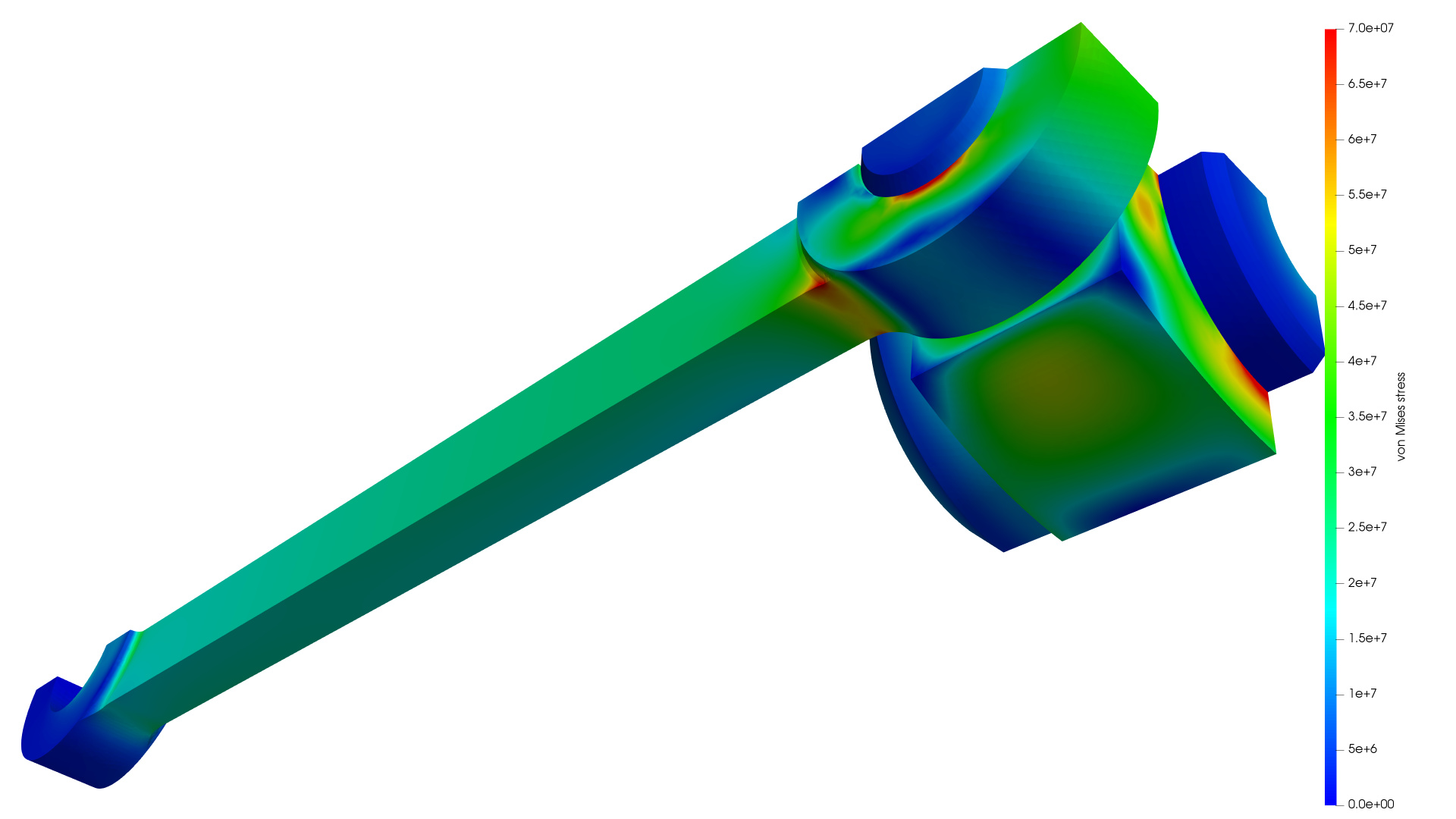
With my first attempt at FEA, I expected to be surprised by the results, and they are definitely interesting, particularly how strongly localised the stress concentrations are. For an assembly where fatigue is not a consideration, it is tempting to read too much into it.
When I had a look late last night (for me) you were on run 7, but you appear to have deleted them now. I presume you were trying various tweaks of the simulation. Is this something I ought to do? In your screenshot, how did you get the longer, prettified scale?
If your loads are correct you don’t have much to worry about. Your maximum stress is only 70 MPa which would be fine even for a fatigue application.
I ran multiple simulations to tune the penalty coefficient. If it is too low you will get a lot of penetration (one part to another). If it is too high it will not solve. I ended up settling on a penalty coefficient of 2e12 for the link to yoke contact. The other two contacts were less problematic.
Physical contacts are like springs that become active when the master and slave surfaces intersect and become inactive when the surfaces separate. The “springs” are connected from every slave node to the nearest master node. You can think of the penalty coefficient as a spring stiffness. Increasing the spring stiffness reduces the penetration but ultimately leads to instability (bouncing or resonance) if too high.