The problem with prescribing the rotation is that I have no way of knowing a priori how far it will rotate; it is entirely dependent upon the torque input, the material specified and its (various) cross-section(s).
To be of any use at all, the simulation would need to allow me to vary each of those three parameters, whilst holding the other two steady.
Eg.
-
Aluminium; 5mm thick; will withstand XXX N.m before transitioning from elastic to plastic deformation and/or shear failure.
-
Mild steel case hardened to 20 microns; needs to be X mm thick to withstand 250N.m of torque without strain hardening and spalling.
-
If space is limited such that we can only accommodate 3 mm thickness in the TA; what tensile strength is required to resist 250N.m of torque.
But that is only scratching the surface [sic] of the scenarios I would like to test.
Eg. Assume I determined that a particular profile of Al 6061-T6 could withstand 200 N.m of torque with a 2:1 safety factor.
Al has the unfortunate property of being subject to early cyclic fatigue failure.
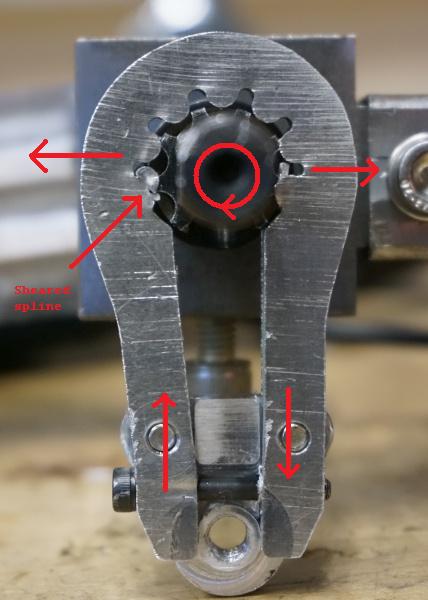
The motors used on (many) e-bikes also do regenerative braking, so the TAs are subjected to repetitive clock-wise and counter-clockwise torque loading that - due to engineering tolerances – subject the TA faces to repeated impact loadings that exceed the nominal torque ratings of the motors by a calculable factor.
Given the manufacturing tolerances for both parts, I can calculate how much unrestrained rotation will occur as the torque load transitions from positive to negative and vice versa. From that, the amount of angular acceleration can be determined and when combined with the area of the axle edge, the impact forces the TA faces must withstand can be calculated.
How many cycles will any given temper of Al withstand before the cycle fatigue induces sufficient enbrittlement that shear failure occurs?
One of the earlier simulations I tried here used a multi-layered spring steel TA. The deign is such that as the axle nut is torqued, the ‘wings’ of the multi-layers close tight around the axle flats to exclude manufacturing tolerances and preclude torque direction transitions from having room to accelerate.
By using spring steel, the idea is to use the materials inherent flex to absorb (convert to heat through friction), and feedback the torque transition loads. Ie. Use material science and Hooke’s Law to resist torque loads, rather than an immoveable object.
In the past, I have led the investigation of a part failure of (eg) a towing bracket welded to the chassis of a heavy truck – that through simulation (Dassault Systèmes SIMULIA + CAD et al) – determined that the failures were due to (welding) heat induced stresses well away from the weld seam.
The simulation of that followed the fracture process from the initial cracks right through to the side of the bracket opening out – several centimetres – to the point that the shackle & eye bolt could detach.
I know such simulations are possible – though it was not my job to construct or run the simulations.
Maybe my experience of (the results from) that expensive commercial system have given me too great expectations of what it is possible (for me?) to hope to achieve with a community account on a system based on OSS software – which can be immensely accomplished and powerful, but is notoriously difficult to setup and use correctly.
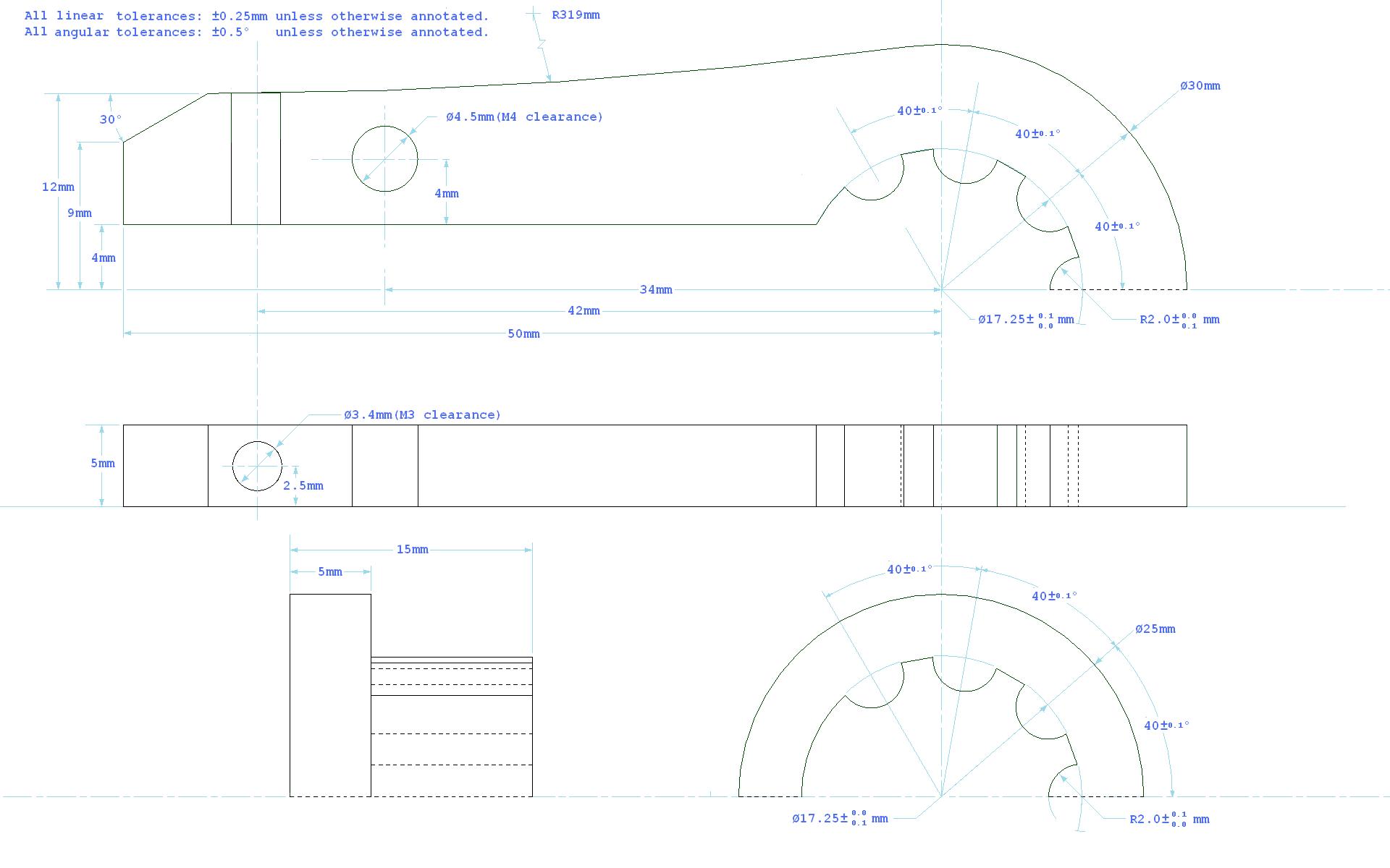
I thought that the splined axle was simple enough that I would be able to gain experience of setting up and running sims here; but if that is too complicated,I stand no chance of simulating the more promising, but complex solutions to the problem I set out to solve.