Hello! I have a problem while I am doing a simulation run for my project. It is a racing car that I designed (STL) in Autodesk Inventor which I put into Simscale to run an aerodynamics simulation.
When I start my simulation run, after about four minutes, I get an error. The bizarre thing is that there is no error log nor anything in the event log apart from ‘Job was prepared successfully.’
Link to project : SimScale
Thanks in advance!
Hi @msaghir,
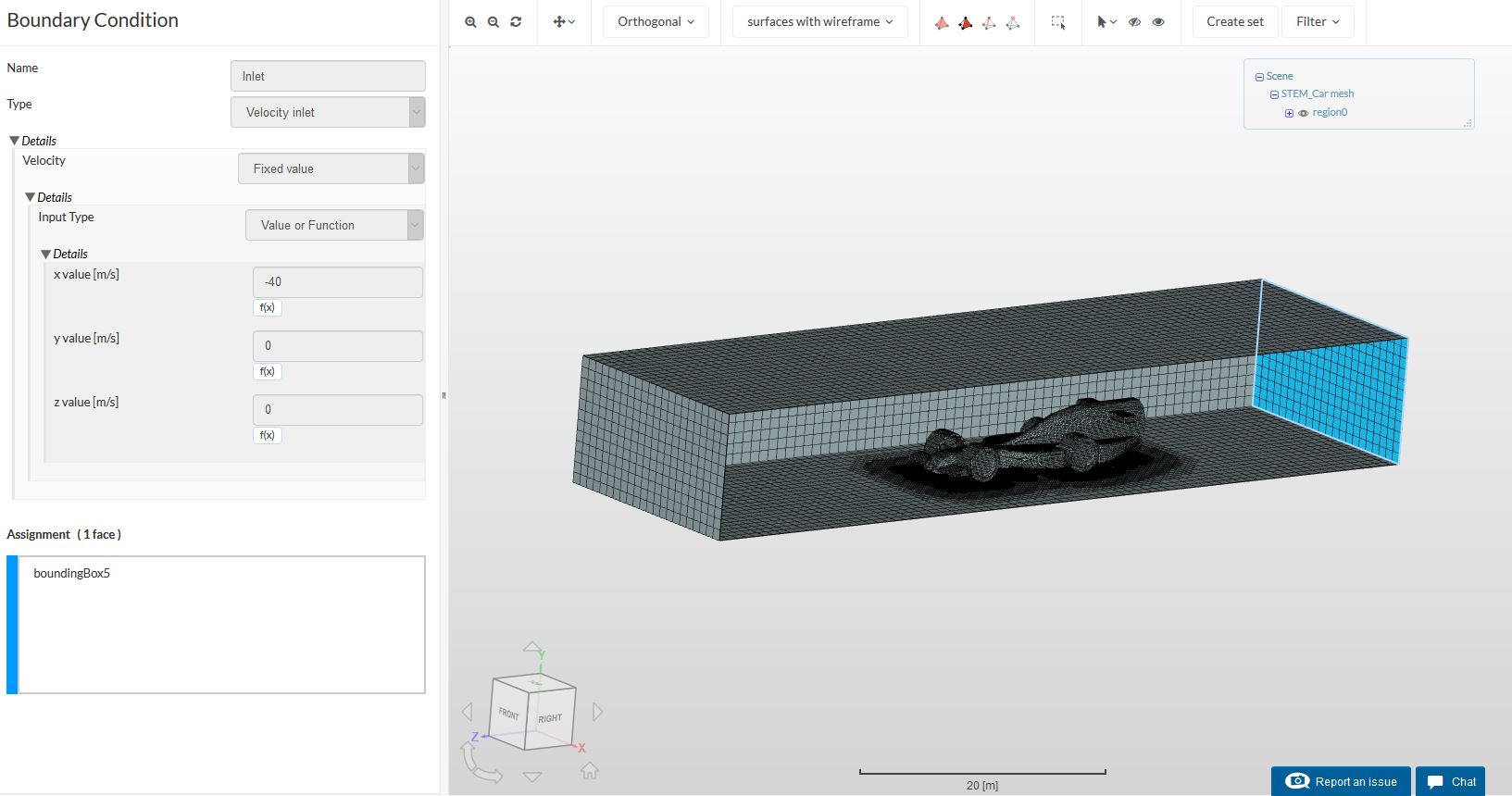
Your errors are caused by wrong definitions of the boundary conditions. Refer to the screenshots of the inlet (first figure) and outlet (second figure) below.
For this figure above regarding your inlet, you will notice that you have assigned the back of the car as the inlet which I assume isn’t what you want to simulate. Also if you note the orientation of the geometry by looking at the 3D navigation cube on the bottom right you will notice that the correct flow direction (once you’ve assigned the correct face which) should be the -Z direction instead of -X. This is what is primarily causing your simulation error.
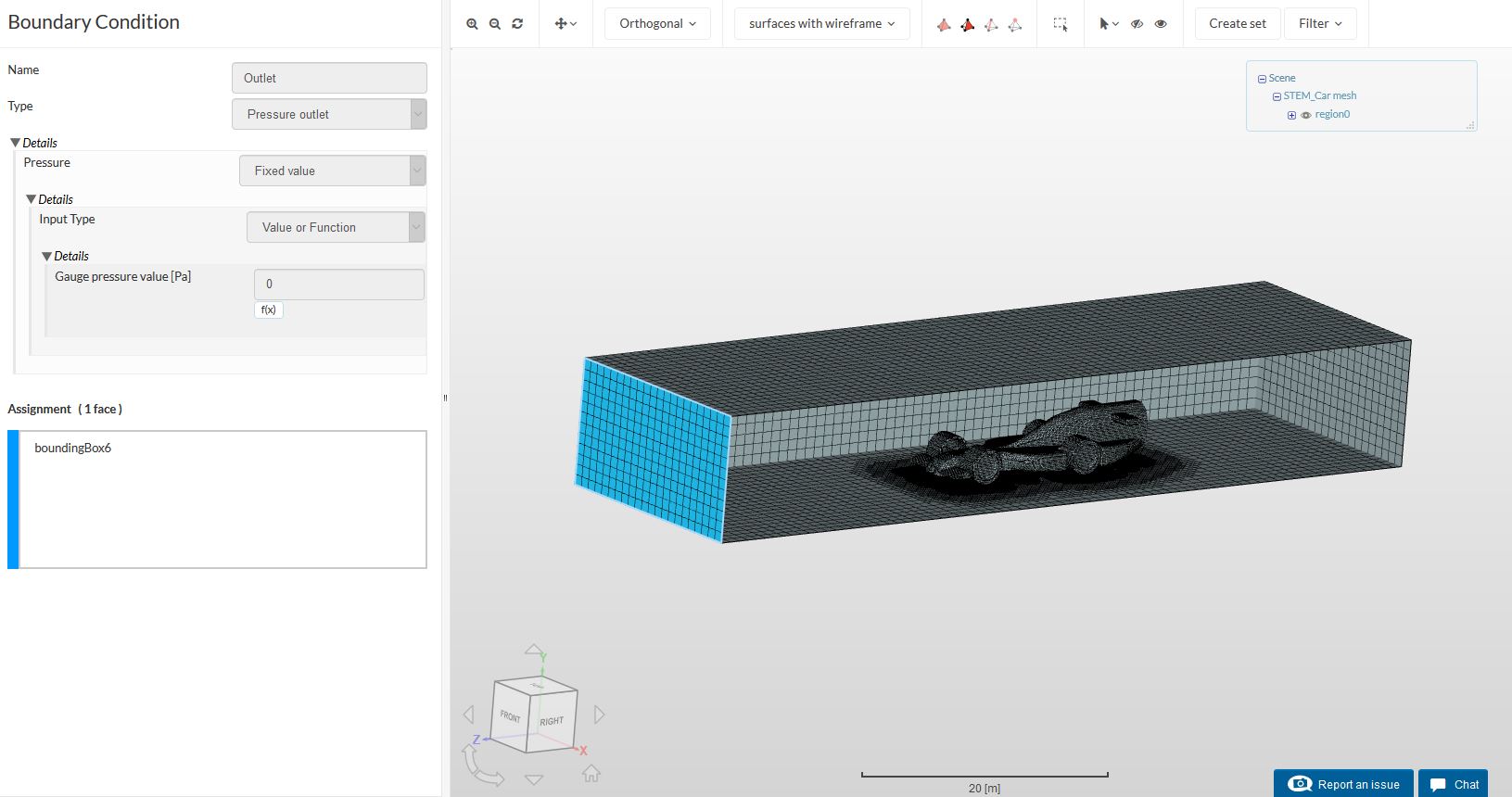
The figure above shows your outlet and while it is the correct type of boundary condition relative to your inlet, I assume that particular face is facing the front of the car and not where you want it to be.
Once you have correctly set your inlet and outlet faces and input the flow velocity to the correct direction your simulation should run fine.
Some other things I saw in your project:
-
Your simulation “Maximum runtime [s]” is still the default. You might want to increase it to say 10,000s so that the simulation wont stop because of the time limit.
-
The “Number of computing cores” you can increase it to 16 cores. That will increase the speed of computation but not 32 as since your mesh is only 793374 nodes the communication time between 32 cores will not result in increased computational speed.
-
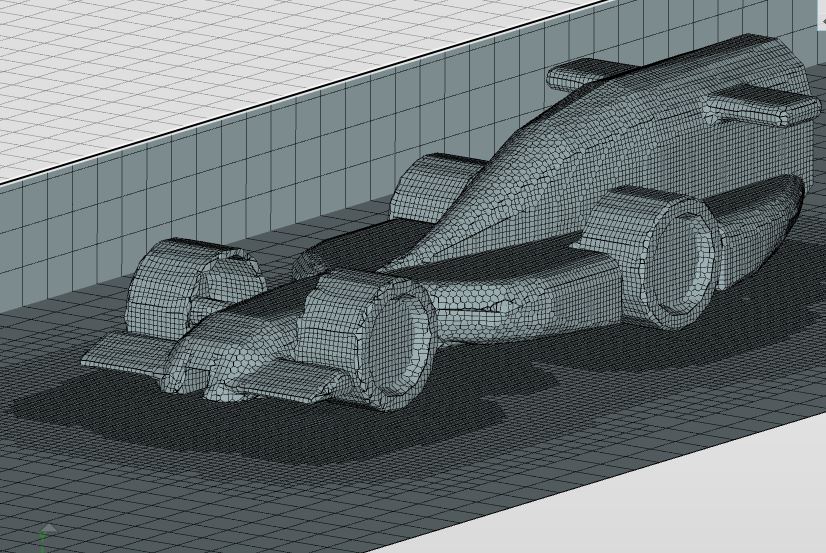
Speaking of your mesh, it is very coarse and that is poor geometry definition as you can see below. This might result in large inaccuracies or poor stability during your simulation. However, you do have zero illegal cells which is great so if the results are unsatisfactory, do increase the fineness.
-
Your wall conditions at the sides and top of the domain could be better defined. You should consider letting the sides of the geometry be slip walls instead of one symmetry. I assume you obtained the idea of the symmetry side wall from some other car simulation project but they define it as such as they have sliced the geometry into two that is identical on both sides in order to reduce computational cost. In your case since it is a full 3D geometry, side slip walls should be more appropriate. This can also be applied to the top of the computational domain.
-
For the floor bounding box it should be no-slip walls as the ground the car is traveling in does act like a wall so you want to capture those effects.
With those points addressed you should get your simulation working. However, when we talk about accuracy several more improvements need to be made which I have briefly stated below.
-
Currently your bounding box is too small and wall effects might interfere with the aerodynamics around your car. You may want to increase the bounding box.
-
You need increased accuracy of the region around the car to better capture the complex flow effects. To do to this you might to switch to the hex-dominant parametric option and take inspiration from this very well done analysis of a vehicle.
-
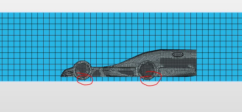
Assuming you want to simulate this geometry actively moving, you will need to ensure that your vehicle actually contacts the floor of the domain. If you refer to the figure below you will notice that it is floating which clearly isn’t what road vehicles do.
Hope this helps.
Cheers.
Regards,
Barry