I am trying to do a simulation to understand passive displacement cooling and I have this error when meshing:
A setup with 5 regions is being used in a single-region analysis type. Please make sure that all regions except for one have an Advanced Concept assigned to them.
This is my first time using simscale so I’m not very familiar with the software but what does this mean? Would appreciate any help, thanks.
The link to my project is here:
Hi!
The error is quite simple. For a convective heat transfer analysis, we only need a single volume (the flow region) for the simulation. The solid volumes, such as walls, humans, etc, should be removed from the CAD model.
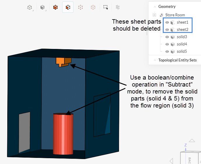
If you don’t do this for a convective heat transfer analysis, you will run into a multi-region mesh error. In your case, I believe the volume named “Solid 3” already represents the flow region, therefore the following operations are necessary:
- Remove the sheet parts from the model (these are never desired in simulations using OpenFOAM/Code Aster). Deleting them should work just fine
- Use a boolean (or combine, depending on the CAD software) to subtract the solid parts from the flow region. This analysis type requires a single volume only (the flow region). The solid parts don’t need to be in the geometry.
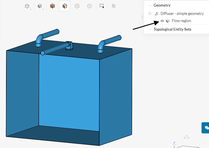
As a result, you should obtain a flow region with the “negative” representation of the solids. Again, the model imported should contain a single volume, like this:
Cheers
Hi!
Thanks for your help. I understand the need for single volume for the simulation, however, if that’s the case, does it mean that I would not be able to simulate with heat sources?
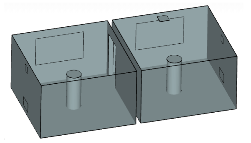
I was trying to recreate a project similar to this project I saw on youtube:
My idea was to have the heat sources from the window and ‘human’. How can I do this?
The orange solid at the top is also the cooling coil that I have placed in the model with the intention to use the different surfaces as inlet and outlet for the air. (left and right are hot air inlet, the bottom is cold air outlet).
Do you have any suggestions on how I can improve my model to make this possible?
Thanks.
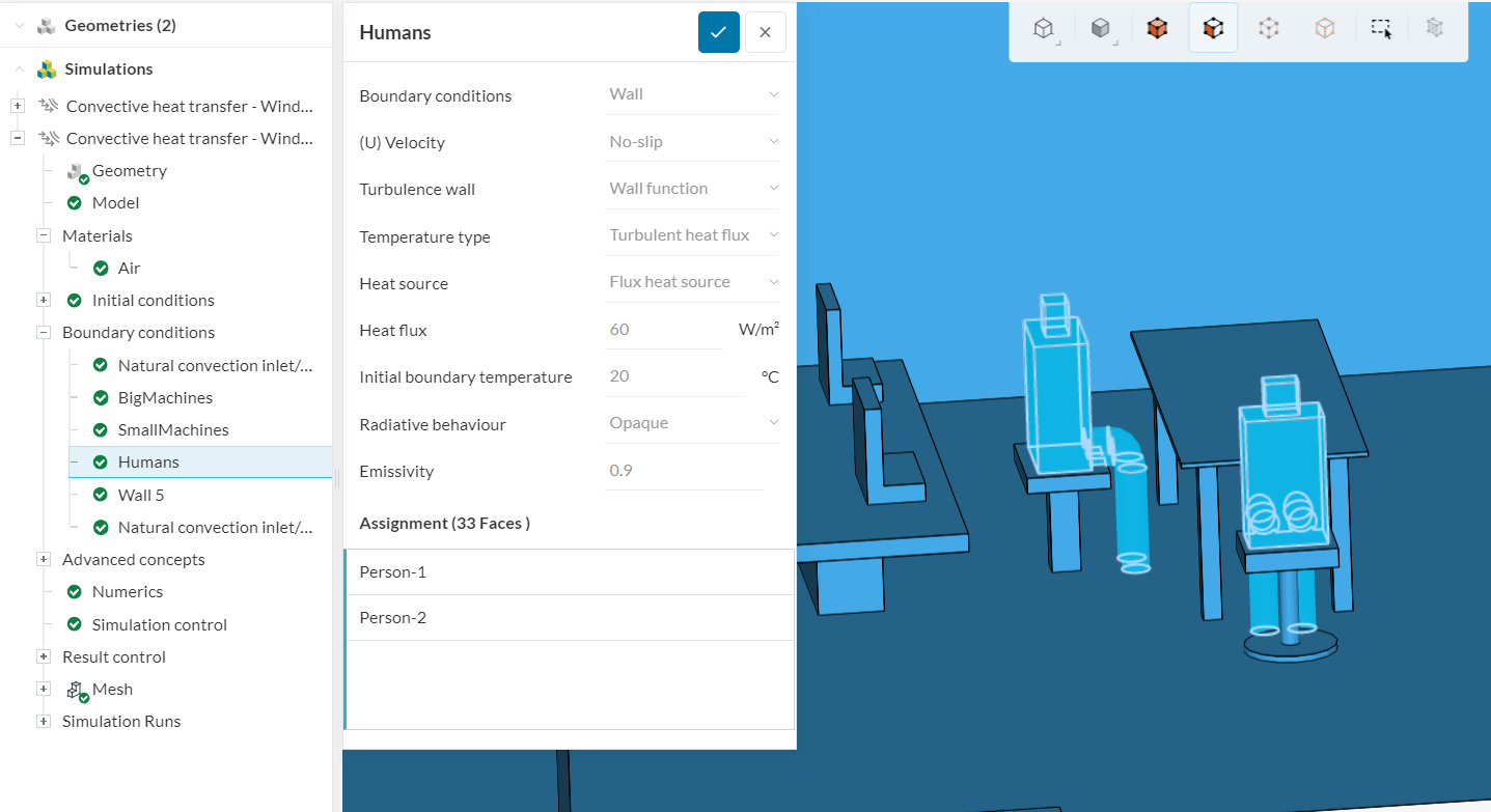
You should be able to model these just fine with boundary conditions. For example, using this demo project as reference, for the humans:
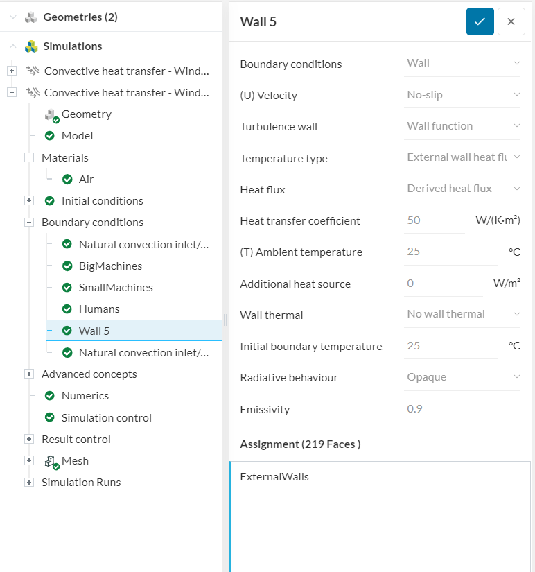
For the windows, normally you would use an external heat flux boundary condition for temperature (probably not with these same values - it depends on the physics of your specific simulation):
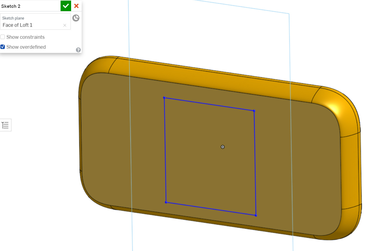
One note about the windows: you would need to create them in your CAD software. One good way to do that is to use a “Split face” operation. First you can create a simple sketch where the windows will be:
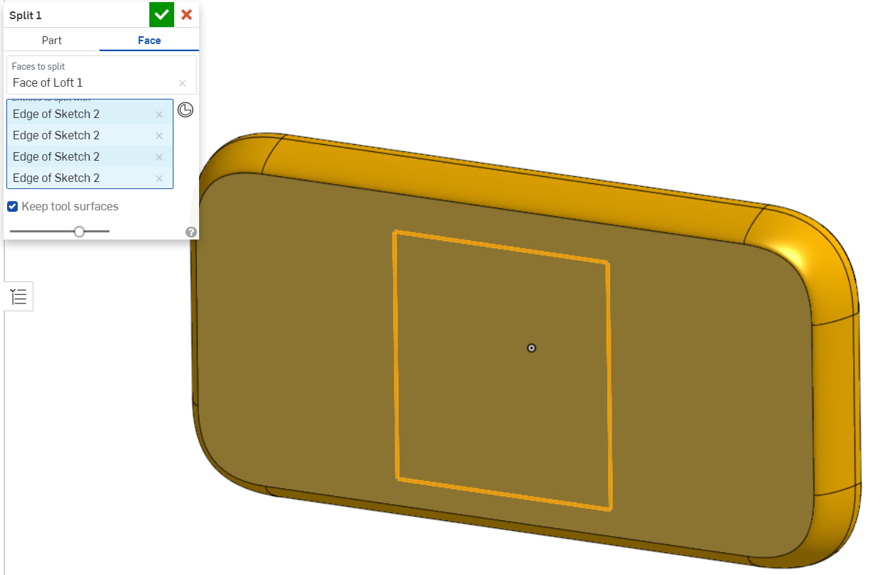
Then you use a split face command, using the sketched lines to split the face:
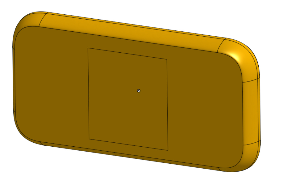
As a result, you should get something like this:
This will allow you to select the window independently from the wall, which will be necessary for the boundary condition assignment.
Cheers