I created a new simulation project called 'ENIAC40 LayerFan':
layer fan
More of my public projects can be found here.
I created a new simulation project called 'ENIAC40 LayerFan':
layer fan
More of my public projects can be found here.
@shaiss - looks like you’re simulating a duct of some sort? One thing to keep in mind is the length of the inlet and outlet domain - it seems to me a very short flow domain. Specifically if you make the inlet domain very short, you will not have a developed flow velocity profile in the duct. Check out this project to understand it a bit better: SimScale Documentation | Online Simulation Software | SimScale Depending on the install situation of your duct you might want to simulate a larger part of the flow domain. Hope that helps
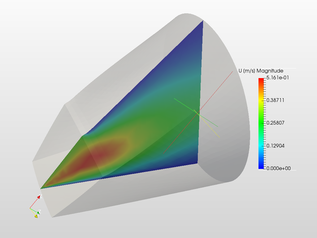
Gave it a quick spin over here: Layer Fan Design CFD Simulation by dheiny | SimScale
Not sure if the setup makes sense. Are you interested in pressure drop? For this inlet and outlet need to be longer!
Best,
David
@dheiny thx for running this!!
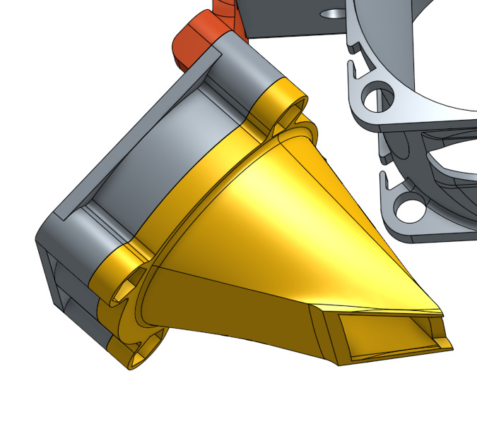
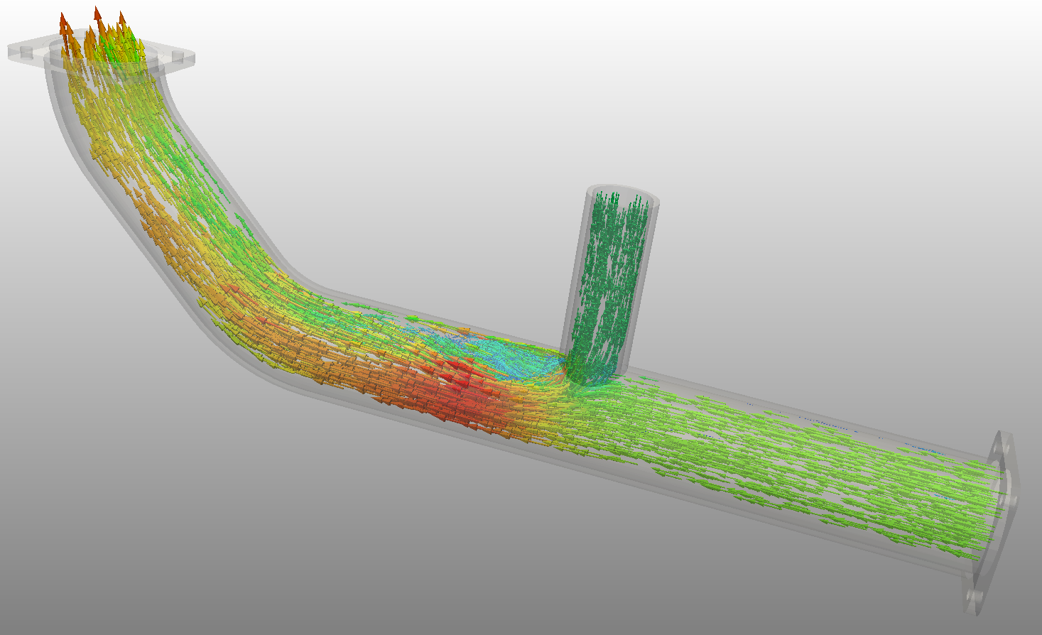
I designed this layer fan, image attached, for a 3d printer hotend. My biggest interest is visualizing airflow within the fuct as how it exits the duct.
The duct itself is very short, ~30mm, as I’m very limited in room. So my goal is to create the most efficient duct that minimize any turbulence, back pressure, and guides the air uniformly out of the outlet (the smaller end).
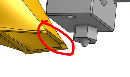
You’ll notice that there’s a small cutout on the outlet top to help guide some air towards the nozzle:
Since this is my first attempt at analyzing and trying to virtually improve the duct I’m learning as I go and open to ideas. My hope is that I can make small iterations and run them through simscale to understand if the changes I made helped or not.
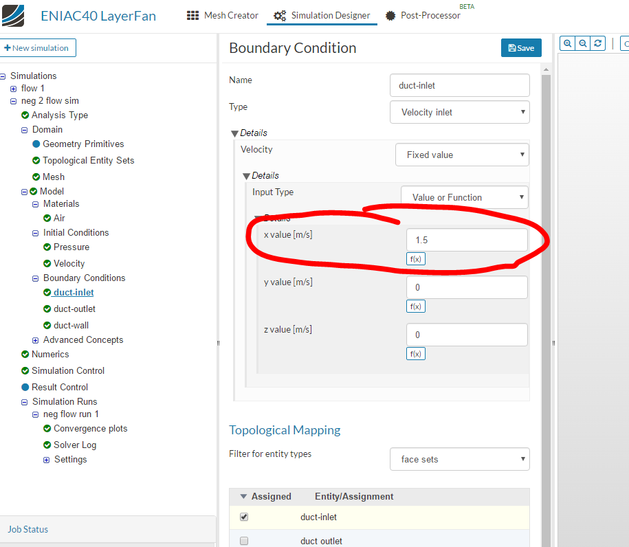
One area I was unsure of was the boundaries and axis to use for the value:
Thanks again for all your help!
OnShape doc @ Onshape
I’d like to see a visualization of my duct just like in the tutorial @
@dheiny I noticed in your simulation you may be using an older mesh I had without the outlet like I highlighted in my previous post.
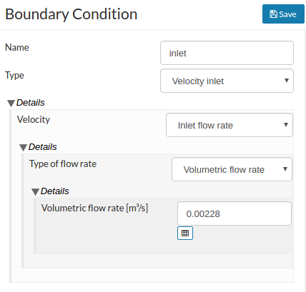
For the boundary condition that’s simple, just use a “Volumetric flow rate” type:
8.2m³/h should be 0.00228 m³/s if I’m not mistaken. Another question: Is the fan directly mounted on that duct?
yes it is screwed into the inlet (the biggest side) and the outlet is about 4mm from the nozzle.
I ran the simulation overnight, need to get back to it and see the results. may run it again with your #s as that’ll be more accurate
Hi @shaiss,
sorry - didn’t have time to continue but now I’ll take a closer look.
To me it feels as if you’re simulating a too small part of the domain/design. You’re interested in bringing as much airflow as possible to the tip of the printer to cool it, right? So I’d simulate the entire printing area to get an accurate image of how your convective heat transfer is working. Or am I missing something?
Best,
David