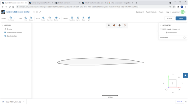
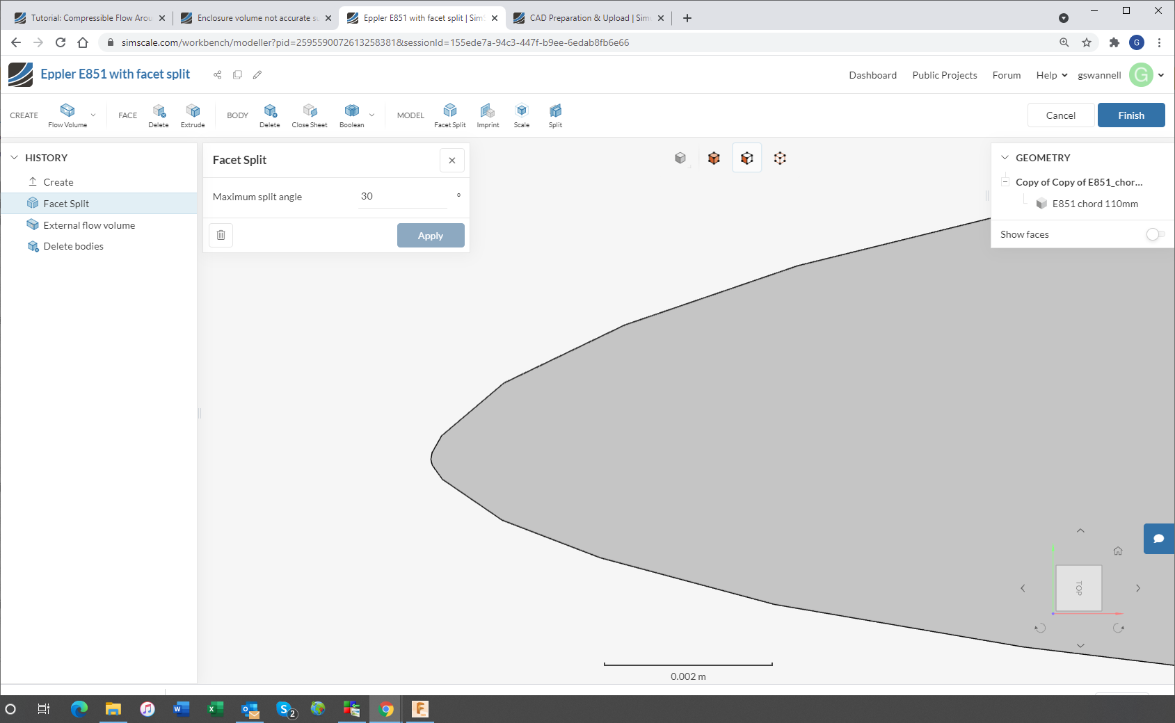
I am new to CFD and having some difficulties learning Simscale for external flow hydrodynamics. My particular question here is about the enclosure and the accuracy of the interface with the part surface, which in this case is an airfoil Eppler E851. I have used the SimScale app to export the airfoil part from Fusion 360 to SimScale. This works fine and the part looks good after importing. (comes in as a Step file). After removing the shape from the enclosure using the CAD Delete function the Copy of the part with the enclosure becomes a Parasolid but the surface interface to the part lacks much detail and is a series of coarse flats, not a small splined airfoil surface. Whether I use a coarse mesh or refined mesh the same shape persists. I would expect this will affect the analysis as the shape of the airfoil is very critical. I wil try and paste some images here.
Yes I thought that might be an option. I have not done that before so would I build a solid body of the enclosure, then remove the airfoil, and then the resulting body export to SimScale. Is that what you are suggesting?
Generate the enclosure body in Fusion 360 and remove the airfoil section body.
Generate a sketch in Fusion 360 of enclosure side view and airfoil and extruding it to required enclosure width which is also a body.
Both methods show reasonable smoothness in Fusion 360 after zooming in and waiting for regeneration.
However when importing into SimScale the result is still a coarse representation of the airfoil.
I have seen examples in SimScale projects where the resulting airfoils have good smoothness so there must be a way to do this I think.
Regards
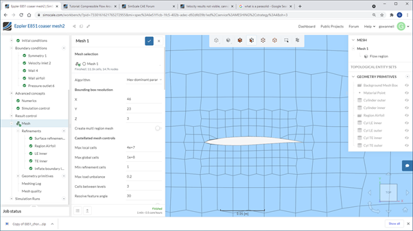
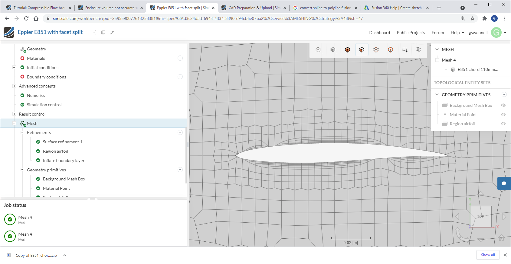
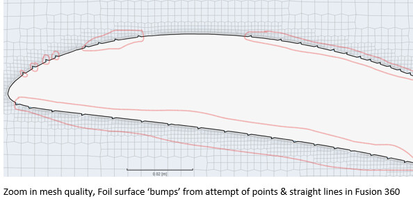
I have found a work around. The problem seems to be the spline representation of the airfoil shape. So I regenerated the airfoil from 64 points to 200 points and imported into Fusion 360 as straight lines between the points. The shape is sufficiently smooth and reads into SimScale OK. See preliminary mesh -more refinement needed yet. One problem is each straight line generates a surface so I end up with lots and lots of surfaces but I can group them to define the airfoil surface. If you do find another way forward I would be interested but I think I can proceed now. Thanks for your help.
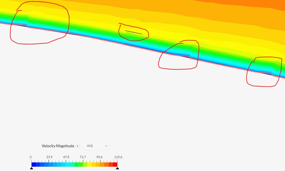
Interesting finding, I have found a similar problem. When Simscale does a CAD transformation the original model imported from the Fusion 360 spline model becomes course with an irregular surface which isn’t in the original model. This has occurred both from a direct transfer from Fusion to Simscale & also when using an imported .STEP file. The upper irregular surface of the airfoil creates small disruptions in the velocity. My data was based on a csv file directly imported into Fusion 360 from Airfoil tools (http://airfoiltools.com/). I think your solution of creating small straights is one way around the issue. Thanks for your idea.
Hi,
I’m wondering if you have resolved the rough surface result that occurs when a part is deleted from the flow volume? I find the issue occurs in the simscale CAD deletion phase, as high zoom in after deletion before Simscale cfd modelling shows the irregular surface. I use Fusion 360 and imported both STEP, STL and also a direct import into Simscale from Fusion 360, but no success.
I’d like to know if you have progressed the matter, thank you for your consideration.
Regards
Chuck
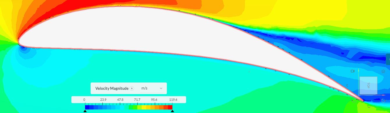
PS: The attachments show the impections I have uncovered. Whilst my calculated lift coefficient from the Simscale lift force is very close, the drag force coefficient is at least twice what is should be, which I put down to the irregular surface profile.
Hi Chuck,
I did not do any more research into this problem since posting my comments in the forum. The work around I mentioned did the job for me so I did not investigate further. I see the imperfections you have and agree that would cause a drag increase. Sorry I cannot help further.
Graham
I tried a small experiment to see if I could improve the refinement of spline imports into Simscale, but no luck. I importing a 10 times larger Fusion Spline model into Simscale and did a 10 times scale reduction in Simscale but no resolution improvement was noted. Segment length remained the same, which were pretty small at the airfoil nose at 0.5mm long, which is pretty small.
No I think the problem maybe in Fusion 360, when you zoom-in very very close the nice curved spline line disappears in the Fusion 360 Design-line/sketch drawing area. The spline curve disappears and you are left with line segments of varying lengths at the nose. The co-ordinate points in Fusion 360 are not actually on the spline line at times. It seems on further examination the ‘regularly’ spaced coordinate points that were imported from Airfoil tools do come into Simscale, but the additional intermediate points created by Fusion 360 spline do not. So what’s it all mean? If you want a better curve in Simscale, I think additional points need to be created in the csv file import, then these will come into Simscale. But trying to estimate intermediate points on a curve then manipulating in Fusion 360 at such a fine level is slow and very tedious. Hope this helps someone.
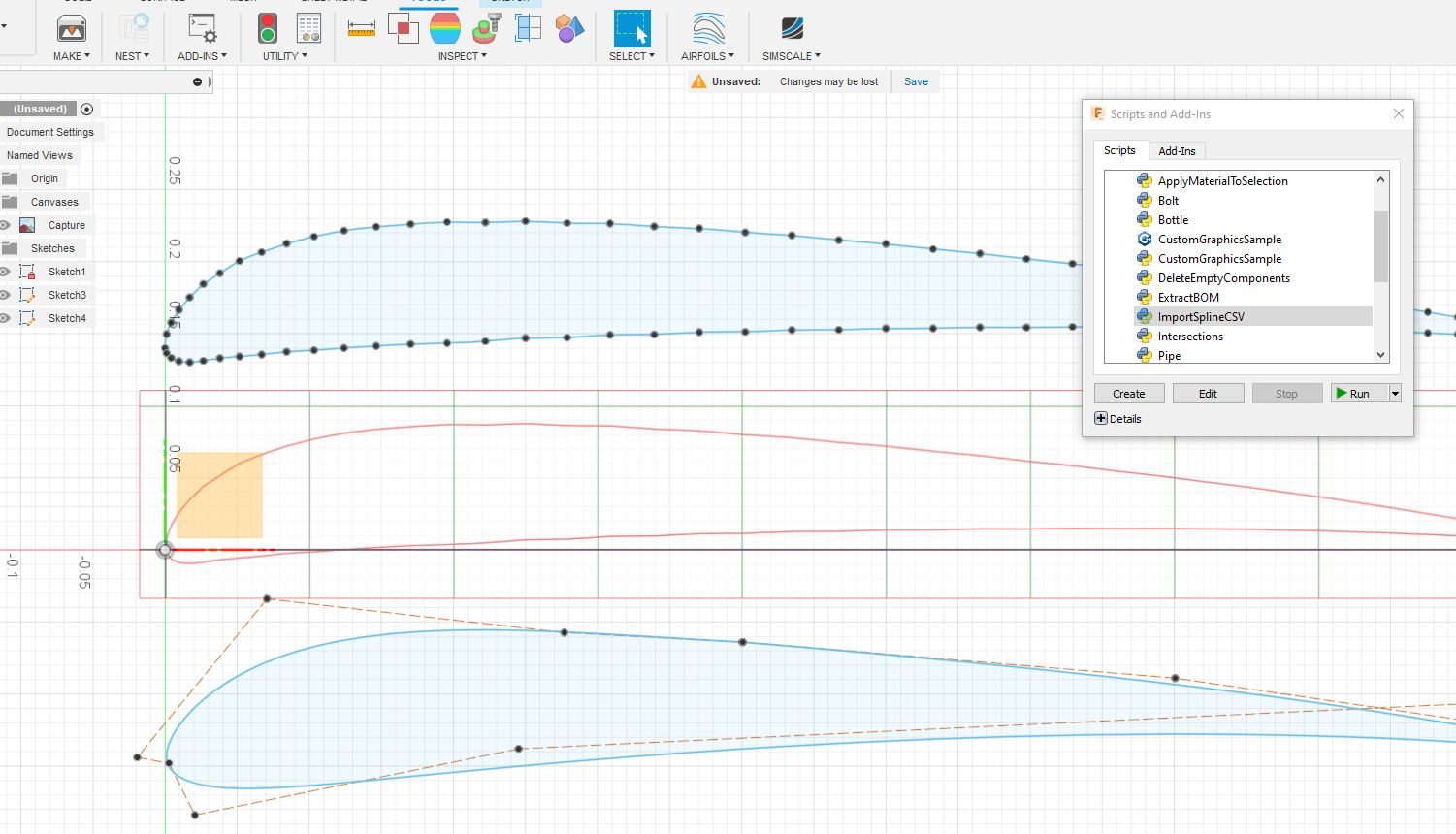
Imported Airfoil co-ordinate points from Airfoil tools to a csv file, then I created an excel airfoil graph of the nominal 80 points and inserted approx 80 intermediate points and ensured the shape was smooth via the excel graph. This doubled the points of the original csv file. I then imported the airfoil csv file into Fusion 360 via the Add-in spline tool for sketching the 2D airfoil shape. I then used the airfoil spline shape as a template to create Fusion points over the top of the imported csv points. I then drew lines between the points to create my own sketch shape. Then extruded the 2D airfoil to a 3D shape in Fusion 360 & imported into Simscale and created a mesh. Result was worse. I’ll need to investigated a better way to draw smooth foil shapes in Fusion 360, maybe Onshape can do this better?
In case you need a simple way to generate more points for an airfoil, I use XFLR5 software. You can set the number of points easily. Also I modified ImportSplineCSV in Fusion360 to ImportLinesCSV for my work around. This may or maynot be of use to you.
Graham
Fusion 360 has two ways to draw splines for curves. Using the “Control Point Spline” rather than “Fit Point Spline” and drawing over an Airfoiltools.com exported airfoil pdf image as a canvas seemed the best. In a large Fusion 360 screen view, with using the 'Control Point Spline" with a few/min points provided me with a smoother airfoil shape when imported into Simscale, as opposed to increased csv coordinate points joined by straight lines. To see that you have an accurate representation of the foil shape drawing on the canvas, I double check this by importing the Airfoiltools foil csv co-ordinates points using the Fusion 360, TOOLS, ADD-INS “ImportSplineCSV” script and place it in the background and check my over-drawing of the pdf sketch against the co-ordinates spline airfoil curve. I find its a lot easier to sketch on the pdf than directly drawing on top of the importSplineCSV sketch as I sometimes hit the coordinate points, when drawing ontop of an imported csv spline, creating confusion. Hope this helps someone