My High School class designed Truss Bridges made of Balsawood and Basswood with onShape and are tying to simulate stress analysis with simScale. There are usually 50+ parts in each bridge. When we try to run the model, we get an error message that says the parts are not connected. I have researched contacts but wonder if there is a simple way to say to contact in place rather than having to specify the master and slave enitities for each connection.
Hey @szoeller!
Thanks a lot for your query. Normally there is a validation rule that gives you warning that multiple solids are not bonded with each other which may lead to either divergence or wrong results. So it is recommended to make the connections between them. I am not sure about the application and how the beams are connected with each other but I would recommend to merge them as much as possible so that you have to define less number of contacts.
For defining the contact, please see the documentation here.
Hope this helps. If you have any question/s, feel free to ask.
Best,
Ahmed
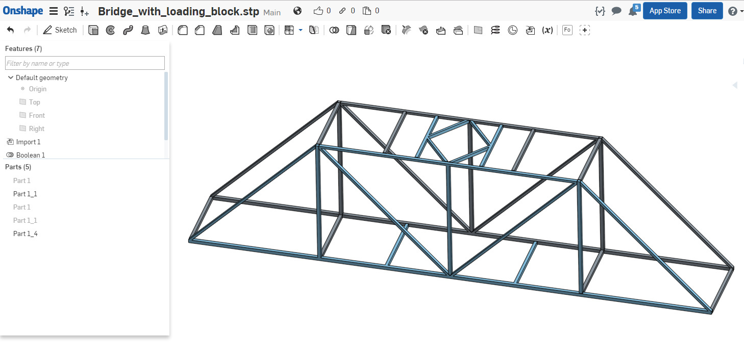
The easiest way to set up this problem is to merge all of the volumes into a single solid using the boolean operation is Onshape - then you do not need to use any contacts at all in SimScale. I took a quick look - and the model merged into 2 parts (the blocks are simply hidden). It seems there are gaps in the model, thus I could not get the full merge.
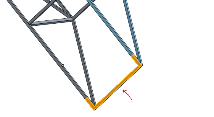
For applying the boundary conditions in SimScale, you can remove the blocks and apply a fixed BC directly at the location where the truss member and block intersect - on both ends
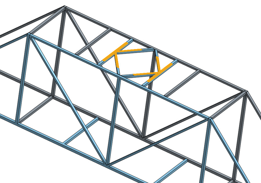
To apply the load in SimScale, you again can remove the box and apply the load directly to the model by applying a force (using m*a)
So,
- In Onshape, create single volume model of the bridge using the Boolean operation
- In Onshape, Use the Split face operation to create the faces for the fixation and load on the model
- Delete the blocks from the model
- Upload only the single volume bridge to SimScale - you will need no contacts in this case
- Perform meshing and apply fixation and force BC’s in SimScale.
Hope this helps
Best,
Anna
5 Likes
I have had difficulty selecting the faces of a part to assign bonded contacts. Merging into a single volume would not be appropriate because the parts are different materials. Using the simulation designer it is difficult to identify the face of the aluminum part that is contact with the plastic part, because they are hidden by the respective solids. As I zoom into the part it seems to go inside and let’s me select the face and assign it in some cases, but not all. Sometimes it only allows selection of the larger part and not the smaller face that is in contact with it. I went back into the meshing tool and had a similar result, by hiding faces I could see into the part to select the proper face, but it would only select both the face on the metal part and the entire side of the plastic part. The parts are assembled with a parallel constraint on the faces and one or two corner edges in OnShape. I’m not done with the full model yet, but wanted to see if I could get these parts to interface before I do too much more.
Hi @chill,
As far as I know you could also leave a small gap between the components and later on decide to numerically “approach” those surfaces.
For the selections you can decide whether you want to chose a face,volume, node or edge in the top menu (see picture).
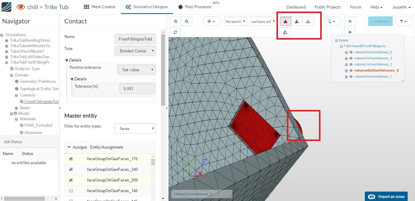
Also fix the overlap also indicated in the picture I posted.
Does that somehow cover your question(s)?
Best,
Jousef
Hi @chill,
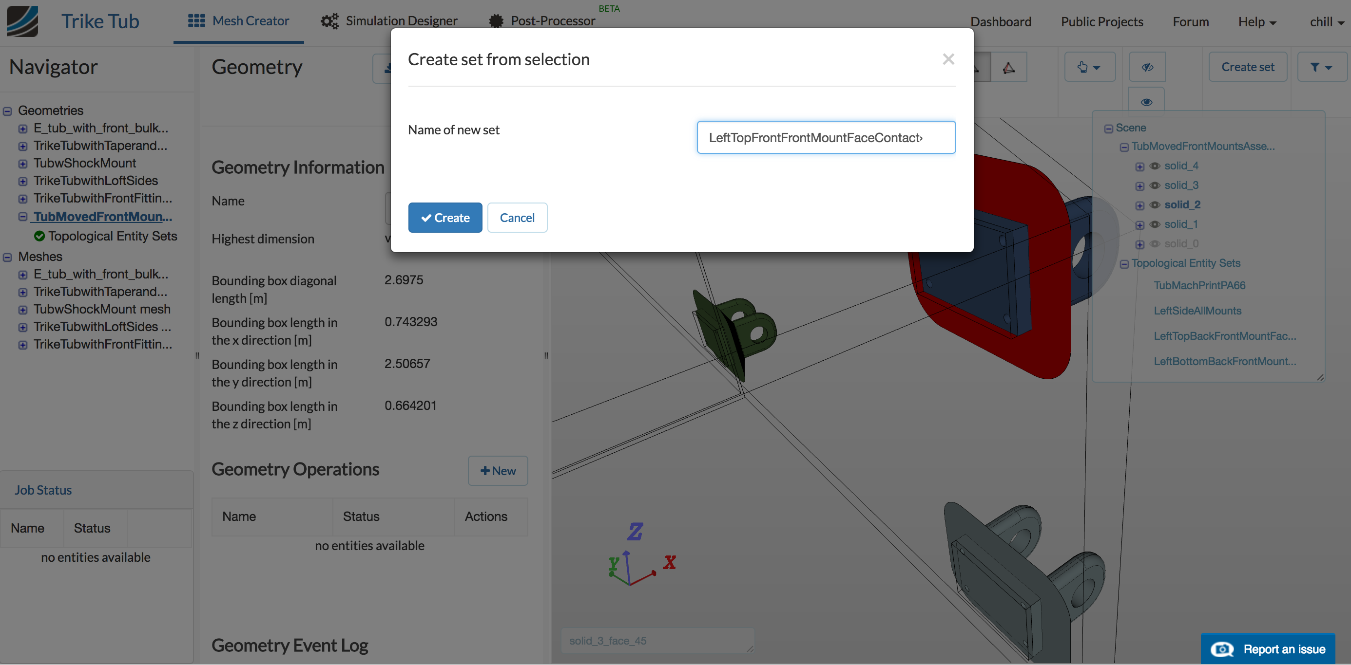
I guess the most effective way to create the assignments for contacts is currently the following:
Imagine we want to create a contact between solid A and solid B.
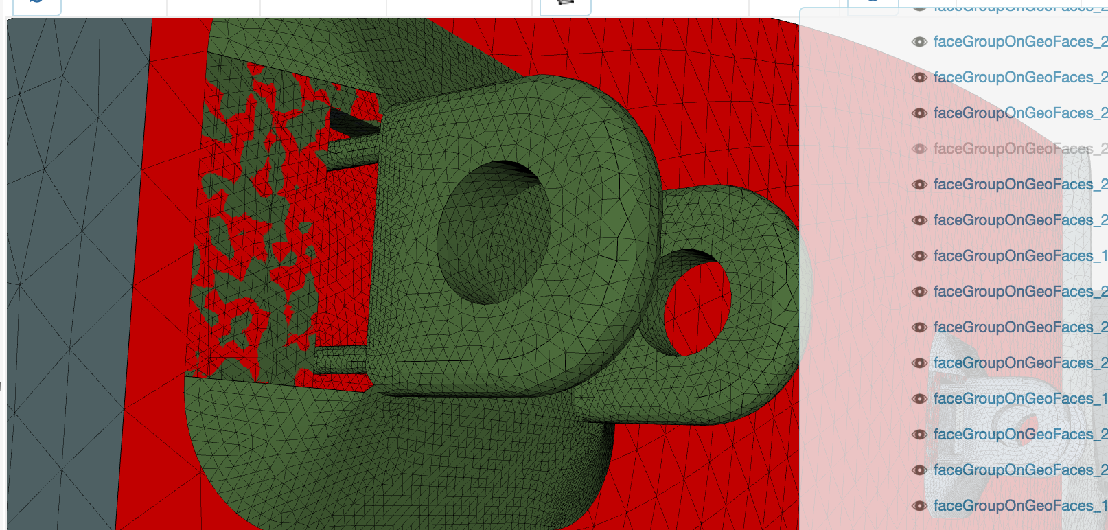
- Hover in the geometry tree (top right in the viewer) over the solids, until you got to solid A. Click in the small eye icon to hide the respective volume.
- Select the contact surfaces on solid B and assign them.
- Right click and select invert visibility. Now only solid A will become visible.
- Select the contact surface on solid A and assign.
I hope this helps.
We are currently planning a rework of the viewer interaction which will hopefully speed this kind of operations up considerably. Stay tuned!
Best,
Richard
Thanks for the quick help. I relocated the front fitting holes before uploading and then created sets in geometry, but they did not re-create in the mesh. It there a setting that carries over the assigned sets? Is there a way to select those sets while setting up bc’s and loads? Using the hide function does enable easier selection of the contact faces in the mesh as well and I was able to assign the bonded contacts to them acceptably in the simulation designer.