Hello All,
I’m trying to validate ductwork to attach to a makeup air unit to ensure the fan can operate at it’s design condition. The existing ductwork was having low flow issues related to static pressure. I’ve run the simulations, but I’m getting quite large negative “pressure” values, and even negative “total pressure” values closer to the fan. This does not make sense.
I have my 6 outlets set to -3 pa to simulate the grilles, and both inlets are set to constant 30,000 cfm. I’m confident in my mesh. I’m expecting a number between 0-0.5” w.g. (0-125 pa) but getting basically no positive “pressure” numbers, which I take to be the static pressure, on my cutting planes.
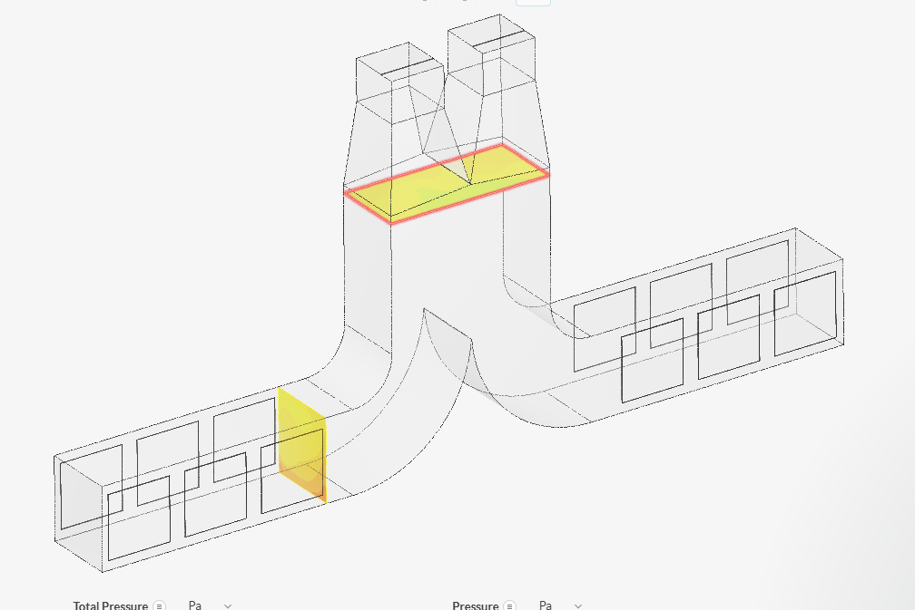
For reference, in the attached image:
- On the large plane, pressure average = -127 pa, total pressure average = -11 pa.
- On the branch plane, pressure average = -8pa, total pressure average = 64 pa.
Do I need to do something different to analyze the static in post processing? Set something else up before running? Any help would be greatly appreciated.