My written log says I did but I could retry.
I like to keep project compact and I delete runs that I make a written note of…
I will try again…
My written log says I did but I could retry.
I like to keep project compact and I delete runs that I make a written note of…
I will try again…
Just Continue the RUN 5 i have created with increased max runtime.
Ah, that is what you changed in your Run 5, I have just started a run like that in my project and noted the change in the sims run name.
Let us pray 
Looking good so far:
Since your Run 5 does not have what mesh was used in the runs name, I am unable to determine which mesh you actually used…
This is one of my biggest complaints of current UI, no way to get that info from previous runs, if you select the Mesh from a completed runs ‘Settings’ tree you only see the currently selected mesh data for the whole simulation ![]() (EDIT I have to eat my words here, I can see what mesh was used in the Sim Runs>Settings>Mesh tree, I just can’t recall this mesh parameters if a mesh has been deleted, I will blame that one on my old age
(EDIT I have to eat my words here, I can see what mesh was used in the Sim Runs>Settings>Mesh tree, I just can’t recall this mesh parameters if a mesh has been deleted, I will blame that one on my old age ![]() )
)
The mesh I am using seems to have better pressures than your ‘Run 5’…
I think the mesh with 3.3 M cells.
Pressure driven flows are really unstable, its quite a problem in CFD. So, firstly, try adding non-orth correctors. Then change all solvers to smooth solvers. Then change the divergence scheme for velocity (div(phi, U)) to bounded gauss upwing, if that doesnt work then were in trouble 
Best,
Darren
Thanks Darren,
I will give that a try later today 
Which inlet BC to use Pressure Inlet Fixed=961 or Total=961 
No worries, I would use total pressure fixed 961, fixed is more stable over mean.
Let me know how it goes,
Darren
But the mean is only selectable on the outlet pressure, I am referring to the inlet pressure…
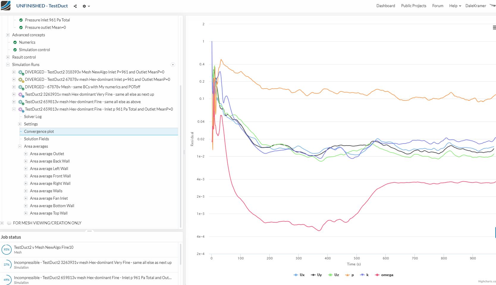
@DaleKramer - Sometimes it’s difficult to root cause it to either mathematics or physics. Before you tweak the math, review results just before and just after the pressure drops to see what is going on. This could be a mesh or turb @ inlet/outlet scenario. If there’s not hing odd there, (and to agree with the general consensus that pressure-driven flow is unstable) you can relax the pressure in the numerics.
I am not sure if this meets your suggestion.
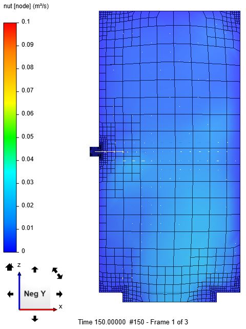
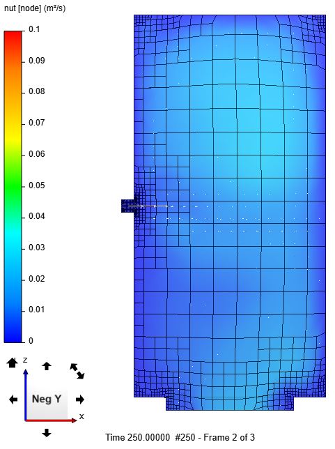
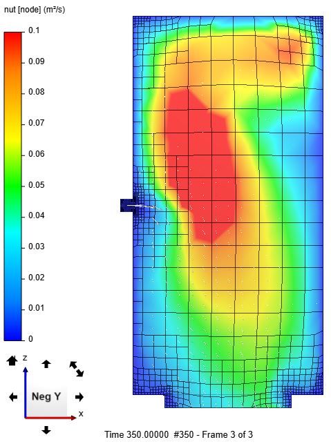
I do not know if these images show a NUT issue.
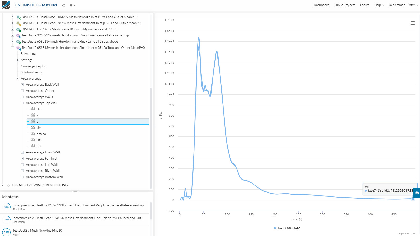
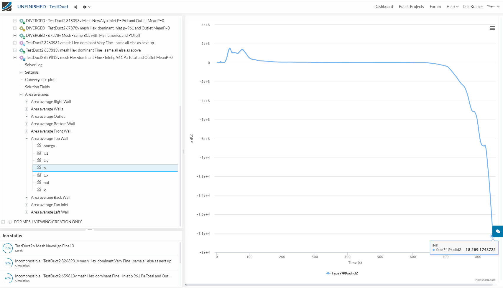
Here is the Average Area Pressure plot on the Top Face.
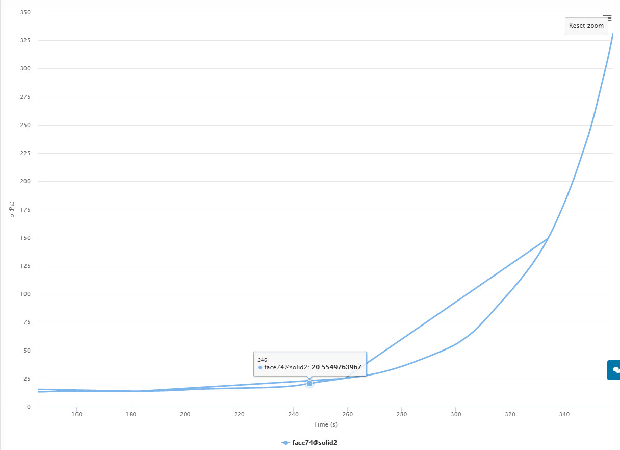
Since I believe that the true result will end up being <20Pa. Then, I would say that at 350s we are into Divergence.
Here is Average Area Pressure plot on the Top Face for 150s to 350s :
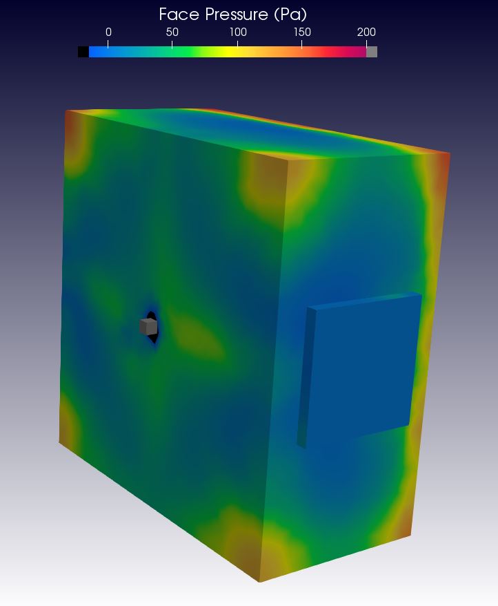
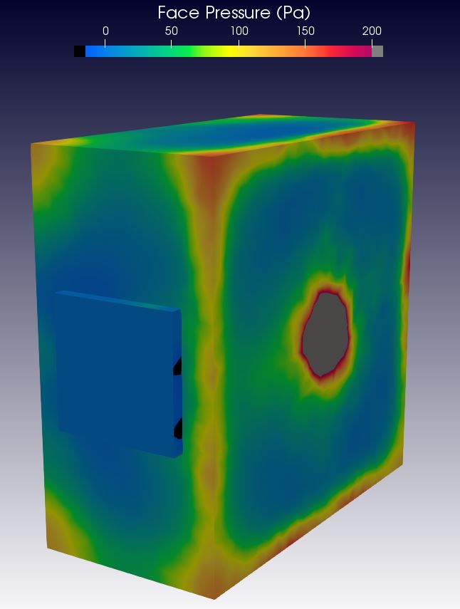
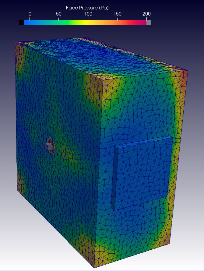
These slices at 150s, 250s and 350s are positioned in the middle of the Inlet and Outlet faces:
Is that the type of ‘pre numerics change’ analysis that you thought should be done ![]()
AND, what does that mean to you ![]()
Thanks,
Dale
**EDIT: It is strange that in this re-run (no changes made, but I needed rerun in order to write data every 50s near the divergence point in order to do this analysis) that the pressure on the Top Face diverges in the +ve direction, while the previous run was a -ve direction of divergence…
Also note that the Top Face is not the top face in these slices, it is the rear face of the slice (I think)**
But Pressure Inlet BC only has parameters for ‘Total Pressure’ or ‘Fixed Value’ (I do not understand what Total Pressure means).
And Pressure Outlet BC has parameters ‘Fixed Value’ or ‘Mean Value’ (Here I would think that Mean value would be easier for code to achieve, in that each cell does not get forced to a fixed value as long as the mean value for the area is matched).
Any comment?
Paralleling this project, I started another one where I am trying to bypass the peculiarities of Pressure driven flow so that I can continue with my duct CFD needs.
I suspected that I can use a Velocity inlet and a Pressure Outlet BC to zero in on the results that I want by iteratively changing the velocity of the Inlet face until I achieve an area average of pressure on the Inlet face that equals 961Pa.
This is the dataset that I needed and it is the one that allows answering the two questions below:
EDIT2 after the proper project setup was developed by @pfernandez here:
Answer to question #1 = 1 PaG
Answer to question #2 = 79 mps
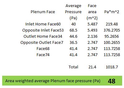
EDIT1: The low quality mesh answer to #1 is 48 Pa and was calculated in this spreadsheet:
EDIT1: The low quality mesh answer to #2 is 118 mps this is how it was iterated:
I first used a guess of 100 mps for the inlet velocity, so then I ran a Velocity Inlet Fixed Ux=100mps - Pressure Outlet Fixed 0Pa BC setup. From that, the results showed an area average pressure on the inlet face of 884 Pa. Since I wanted 961 Pa on that face I simply increased the Inlet velocity from 100 to (961/884)^.5 or to 118 mps… Then I ran the sim at 118 mps and I found that pressure result was 960 Pa as was required ![]()
SO, this iterative method works and I was able to get my results in only 2 simulation runs ![]()
![]()
![]()
![]()
![]()
![]()
Since I can continue my work by using this iterative method, I may just leave this Pressure driven flow topic in an uncompleted state for now.
Perhaps someone else can finish this up and develop my Pressure driven project so that it gives the same results as the iterative method ![]()
In the meantime, I will mark this as the solution to my topic. (I know it is a workaround but I will give the person who truly figures out how to answer this using Pressure driven flow the solution checkmark when they post the answer here ![]() )
)
EDIT1: I further determined that an iterative method of Velocity Inlet/Pressure Outlet used less than 1/2 the core hours of an iterative method using Pressure Inlet/Velocity Outlet…
Wow, another one of my super long topics, oh well, thanks all…
And just because these are so cool ![]()
“When in doubt, make it velocity-driven!” haha - hard to argue with this work around to be honest.
Did you use the same grid density for both analyses?
Hard to tell by the screenshot, but my initial reaction is your inlet duct mesh is very coarse with only 1 element across the entry and 1 element “upstream”. To truly resolve the flow you will need to bump it to 5-10 D upstream length as well as perhaps 10-20 across the width to resolve the flow and BL properly. Additionally, this is a classic “jet” scenario, where a small fast flow enters a large slow volume. The preferred turb model in this case would be the K-O or K-O SST (HERE). (My two cents despite not having reviewed the analysis in detail!)
Yes, I will be doing much finer meshes now that I have a BC method and sims that converge and thanks for link on relevant turb model…
Hi @DaleKramer,
Looks like an interesting project for a grid independence analysis and some other kinds of validation. So I was just playing around with a structured mesh I created locally. You can find the project here. Feel free to take the mesh for for your own analyses.
So far—simulation are not fully converged yet—I’m getting results both for pressure inlet and velocity inlet boundary conditions. Those results are quite different from yours; although this could be very likely the differences in mesh resolution.
I also tried both incompressible and compressible solvers, as at 118 m/s the incompressibility assumption is no longer valid (Mach > 0.3).
It might also be worth extruding further both inlet and outlet boundaries so that we get fully developed flows—at least to avoid backflow at the outlet.
Cheers,
Very cool, imported structured mesh, I have to learn how to do that
I am not relying on my answers to my 2 questions yet, I know much better mesh will change results, I was just excited I had a method to gets results…
Since that 118mps (mach 0.34) slows down so quickly in the plenum, I was hoping to stay incompressible.
Maybe with a better mesh that Inlet would be less than mach 0.3 at 960Pa inlet and 0Pa outlet
I think the inlet and outlet extensions would likely help in convergence but it is straying from the real world setup I have…