Ducting Boundary conditions for known inlet duct gage pressure and an outlet that sends air into the atmosphere at 0 Pa gage

Very cool, imported structured mesh, I have to learn how to do that :wink:

I am not relying on my answers to my 2 questions yet, I know much better mesh will change results, I was just excited I had a method to gets results…

Since that 118mps (mach 0.34) slows down so quickly in the plenum, I was hoping to stay incompressible.

Maybe with a better mesh that Inlet would be less than mach 0.3 at 960Pa inlet and 0Pa outlet :wink:

I think the inlet and outlet extensions would likely help in convergence but it is straying from the real world setup I have…

1 Like

I just had a look at the both incompressible and compressible simulations, and the results are far too different, area average velocity inlet is showing around 190 m/s (Compressible Pressure driven) and area average pressure inlet is showing around 101484 instead of 102286 Pa (Compressible velocity driven).

Here is the 50mm fan I am using, 118 mps sounds a little high but it really whines :wink:

1 Like

EDF Motor rating in KV (RPM/Volt)? Just for information.

1 Like

Those results being different is ok, or at least consistent:

  • Pressure driven: I specify an inlet pressure of 102286 Pa (101325 + 961 Pa). Still not fully converged, but solution seems > 200 m/s.
  • Velocity driven: I specify an inlet velocity of 118 m/s (Dale’s result from a coarse mesh). The solver computes an inlet pressure of 101484 Pa (101325 + 159 Pa).

On a finer mesh, the solver is estimating a much lower pressure drop in order to reach a velocity of 118 m/s at the inlet. If I impose a higher pressure drop (961 vs 159), it follows that the velocity will be higher as well—all other things equal.

1 Like

But can a small hobby EDF BLDC motor rotating at around 60000 rpm able to displace air at around 200 m/s. It is too much.

I have copied your project and will play with the mesh, seems to me that your sim runs looked sorta converged on the residuals but I never saw any results that were stable at all, I will look again and extend some of your runs looking for stable average values on faces …

1 Like

Although it’s been a long time since I studied jet engines and have had no experience with hobby motors, I would agree with you that this velocity might be too much. But I’d go further, and question also the given pressure value.

So, why don’t we start over and validate our assumptions? It wouldn’t do me any harm to refresh some of the concepts I’ve seen back in college. So,

  • Is the 961 Pa measured or calculated?
    • If measured: what’s the accuracy of the sensor, and were and how is it placed? Might be it is not measuring pure static pressure.
    • If calculated: how can we go from 770 g of thrust—fan datasheet—to static pressure?

We can then go on digging until we find an optimal result.

Cheers.

2 Likes

Well I took 770g over the area of the 50 mm duct and got 961 Pa, which I see now that you make me look at my spreadsheet, is INCORRECT. I forgot to divide the diameter by 2 to get radius… so area should be:
pi*(.05/2)^2 = 0.00196 m^2 and pressure would be 770/0.00196 = 392158 g/m^2 or 3846 Pa… OOOPS…

I need to take foot out of mouth and reconsider what is going on here…

I have measured an internal gage pressure on a ~0.028m^3 plenum with full rpm fan and with no plenum outlet (air just backflows out of fan duct) and get 2200 Pa on my accurate differential pressure gage.

Here is that setup:


I will measure the actual free air thrust I get and report, I hope it is 770g :wink:

1 Like

This is getting interesting.

Thing is, a higher pressure would mean a higher velocity, which is not good. Also, the static pressure jump on a fan depends on the mass flow rate through the fan, and from your setup I would assume a near 0 mass flow as you are pumping into a closed volume.

image

Now, I’ve been searching around and found a nice article from NASA on propeller thrust. According to the article

F = A\Delta p

where \Delta p is a total pressure jump. So, we should be using total pressure instead of static pressure, which is kinda good news.

We can also estimate the velocity at the exit from the pressure jump, as

\Delta p = \frac{1}{2} \rho (V_e^2 - V_0^2)

Let’s try with a total pressure inlet boundary condition, and see what we get.

2 Likes

I’ve obtained some promising results by using a total pressure inlet boundary condition with the compressible solver. Incompressible was not diverging, but results were all over the place, so I’m ignoring that for the moment. Both were using the default settings, so tweaking the numerics might help in the incompressible case.

Anyway, with compressible solver, results converged in 1000 iterations to the following values:

  • Ux: 78.8 m/s
  • p: 101425 Pa (100 Pa, relative)

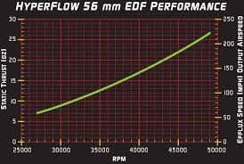
Those results look reasonable to me. For comparison, I found the following chart—I presume it is for a similar type of fan—and results are of similar magnitude.

  • 770 g → 27.1 oz
  • 78.8 m/s → 176 mph

imagen

Reminder: link to project here.

2 Likes

WOW, you did it :star_struck:

It does make sense that Total Pressure would be more correct and just for the heck of it I will make a run as if I did a test as hurricane Dorian was passing by :wink:

Thanks for your research that has provided significant validation and I will revisit some of my finer meshes with the Compressible(kw-SST)-TotalPressure method using 3846 Pa difference between Inlet and Outlet…

As of right now, it looks like your last Compressible Run 1 had pretty stable results values and could be considered quite usable :slight_smile:

Thanks again,
Dale

2 Likes

In your last Compressible Run 1, you ask for 105171 Pa on the inlet face and 101325 Pa on the outlet face…

And the apparently ‘residual converged’ and stable results shows only 101425 Pa on the inlet face…

This is likely a stupid question, but what happened to the 3846 PaG that we thought we had (770g / 50mmDia) :question:

Edit: At 100 PaG, the inlet has only ~20g of force applied to it, not 770g… (also the area of this square test duct inlet is a little bigger than the 50mm diameter fan, so that accounts for a little difference somewhere)

Recall from NASA’s article that the thrust is the total pressure difference, not the static pressure difference. So, 3846 Pa is total pressure difference.

101325 Pa is the freestream total pressure, which is equal to the static pressure because your fan is stationary (V0 = 0 m/s)

The fan adds momentum to the flow resulting in 770 g of thrust. So, the total pressure behind the fan is the total pressure before the fan (101325 Pa) plus the total pressure delta (3846 Pa) = 105171 Pa. This is the total pressure at the inlet of the domain, behind your fan.

I hope this clears things up.

PS: you can check that 100 Pa + 0.5 * 1.206 * 78.8**2 ~ 3846 Pa

Sortof cleared up but the results show only 101425 Pa on the inlet, that is total pressure isn’t it?

How do we see the 770g of thrust in the results?

EDIT: Aha, your edit answered that :wink:

p is static pressure. If you want total pressure you can calculate it yourself:

100 Pa + 0.5 * 1.206 kg/m^3 * (78.8 m/s)^2 ~ 3846 Pa which is your total pressure delta.

1 Like

So then when your results for All Walls pressure is only 1 Pa above the outlet pressure, that 1 Pa is a 1 PaG, which, unfortunately for me, is very low and sends me in another direction on my project :frowning:

Yes, the average pressure over all the walls will be just 1 Pag; but you should see and overpressure in the wall oposing the jet.

In my mesh, I have a single face Id for all the walls, but depending on your objectives it might be a good option to split the walls into more faces and get average values for each one of them separately.

1 Like

And if we were in the eye of hurricane Dorian at 913.4 mbar, we would have:

  • Ux: 83 m/s
  • p: 91445 Pa ( 105 Pa , relative)

:wink:

1 Like