I’m trying to analyze a ducted fan where the boundary inlet and outlet is the duct’s actual inlet and outlet. There are three bodies: the fan, the duct and the zone of rotation around the fan (for I’ve tried internal meshing first and tried different variations of the material point: inside the body, outside the body but inside the duct, etc. Whatever I do, meshing fails and there’s no error message or meshing log. What am I doing wrong? I suspect the devil is in the mesh refinement details…
Hi @glorincz,
Copied your project over [here][Deleted by author] and meshed fine after i tuned some settings. Maintain these settings and adjust the refinement levels as needed.
Do screenshot the settings as I don’t keep user projects for long. Usually a week or so.
Cheers.
Regards,
Barry
1 Like
Thank you! I have managed to create the mesh with your settings, however I keep getting an error when trying to run the simulation.
Missing material assignment for the following entities: prop
The propeller/fan is supposed to be solid, right? Not sure how to proceed.
Hi @glorincz,
You need to simply select the air assignment for the entire geometry as shown below. No need to split material assignments. While this might not seem to make sense as your prop is not made of air, but we equally need to define what the prop’s medium is going to be. We will redefine the prop as a full solid in the boundary conditions later. Refer to the screenshot below to see what you need to reassign.
Cheers.
Regards,
Barry
1 Like
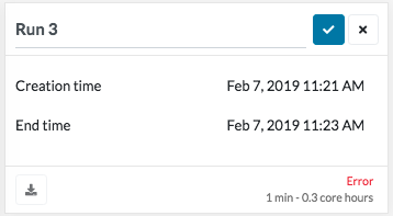
Makes sense! I assigned the material to the whole geometry and when I ran the simulation I got an error (but no description of what the problem might be).
Hi @glorincz,
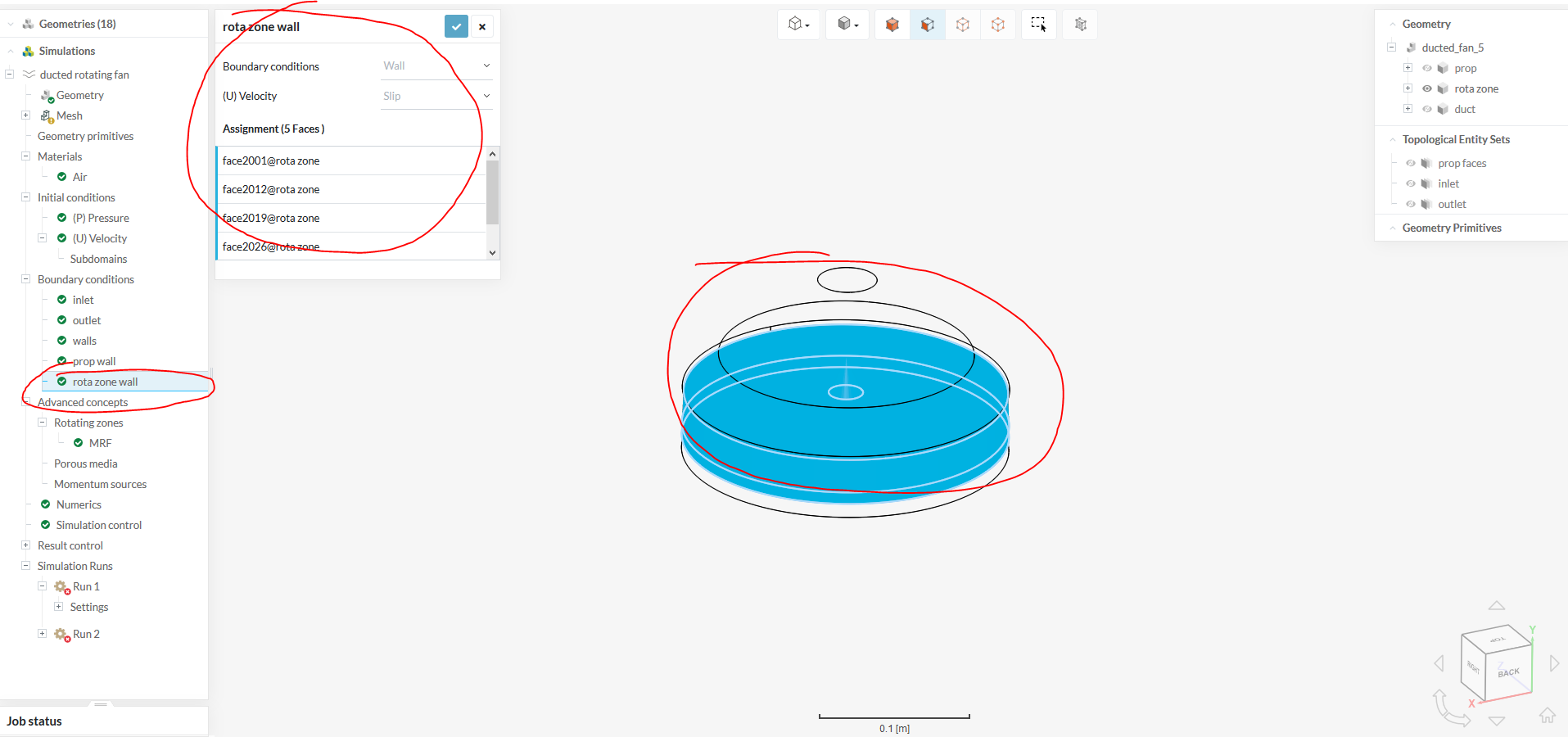
You’ve run into an instant error as you have a mix of incompatible BCs namely the slip wall implementation onto the rot zone which already has the correct MRF assignment. Remove the assignment as highlighted in the figure below and it should run fine.
Also you should assign a simple force plot for result control onto the prop in order to monitor convergence.
Cheers.
Regards,
Barry
1 Like
I have removed the said boundary condition and I still get error but not an actual description of what went wrong. IS there a log for the simulation?
@glorincz, you have an additional cell zone, where the blades have meshed, this is not required. To remedy this, I think I would try removing the propeller geometry but instead, remove it from the fluid part. i.e. a Boolean operation removing the ‘prop’ from the ‘duct’ but keeping the rotating zone in the geometry of course.
Best,
Darren
This is what I did: I applied a boolean cut (prop from duct) so now the prop body is gone, instead there’s a prop-shaped hollow cavity. What I don’t know is what refinements should I add? Thank you for your help!
So from there you should refine the prop, surface refinement without cell zone and then the rotating zone, surface refinement with cell zone, after the mesh you should have 2 cell zones region0 and the MRF zone (no prop).
Best,
Darren
@dlynch I’ve tried that and I get an error:
An internal mesh could not be created as the geometry model consists at partly of surface data. Please try to solidify these parts.
What am I doing wrong? I’ve even changed the material point to be outside the zone and the fan but inside the duct.
I get this error when meshing. I’ve been trying to make this project work for days and I feel like I’m getting further and further from ever finishing it. I used to be able to mesh this but then I couldn’t simulate it (there were errors w no actual messages). Now I can’t even mesh it. I tried moving the material point but it does not make any difference. Could anyone actually look at it and tell me how to fix it?
SimScale (second simulation, ducted rotating fan w boolean cut)
Hi @glorincz!
I saw that you have received help from Barry and Darren in another post. Creating a separate post usually won’t help faster but makes things a bit messier - just something to keep in mind for future issues 
Will have a look at your project and see if we can make this work. Could you explain crisply what the shape is for? Otherwise I would have just put the propeller with a surrounding cylinder into a big domain. Once that is clarified I have a bigger picture of your project and can start with setting it up.
Best,
Jousef
Thank you for merging the two topics. I want a rotating fan in a duct with internal meshing (I’m only interested in the airflow inside the duct). Right now the geometry consists of the duct with the propeller cut out (therefor there’s a propeller shaped hollow cavity) as Darren suggested. There’s also a rotating zone around the prop, inside the duct. So I have two bodies to mesh, the duct with the rotating zone inside. I just want to be able to mesh it and run an incompressible flow sim. It seems so simple: I added and inlet and an outlet, refined the surface of the fan, defined walls, etc. I need help to make this work and understand why it didn’t work. I’m forever grateful for Darren and Barry but I’m confused right now. Thanks for your help (as always!)
SimScale (second simulation)
I see @glorincz!
Why don’t you simply create an internal flow analysis with a MRF approach for the fan? It is way more representative for the setup as using the big background mesh for external flow simulations. The boundaries of the box won’t affect the fan anyway as it is enclosed into the duct, makes sense? So I would extend the inlet and outlet length of the duct and keep the fan. We would then create a rotating zone for the fan and simply assign an inlet & outlet for the duct. Saves us cells, is more representative and realistic for this case and will be faster in the end.
Let me know if I missed your point here but I think we should proceed that way if I understood your project correctly.
Best,
Jousef
1 Like
Why don’t you simply create an internal flow analysis with a MRF approach for the fan?
This is exactly what I want.
So I would extend the inlet …
After reading this I noticed that the MRF zone ‘sticks out’ out the duct. Fixed! Thank you!
We would then create a rotating zone for the fan …
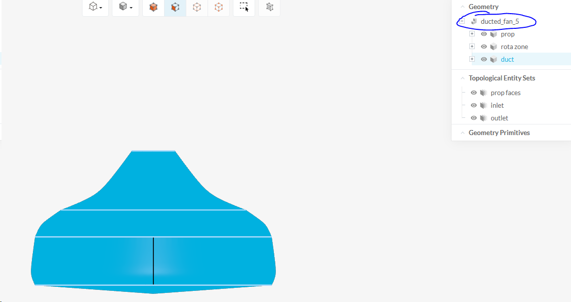
There is a rotating zone created as a body. The geometry has three parts: duct, prop and the zone around the prop (but inside the duct). Am I supposed to create the rotating zone as a geometry primitive (instead of creating one in the 3D design software I’m using)?
I started the whole thing from the scratch and now I get the ‘missing material assignment’ for the prop. Why? I’ve set meshing to internal and even tried moving the material point outside the prop but it does not make any difference. Am I missing a meshing refinement? How do I define the prop as a solid?
Hi @glorincz,
I’ve copied your project over again. Let me work on it and get back to you.
Can you provide info on what is the data point you are looking for? Drag? Lift? Mass flow?
How are you determining whether the simulation has met your objectives or not? From there I can perform runs on my side to and see how close/far they are and where needs to be improved.
Cheers.
Regards,
Barry
EDIT: Completed the simulation. You can refer to the project [here][Deleted by author]
Here are some screenshots to verify the physics.
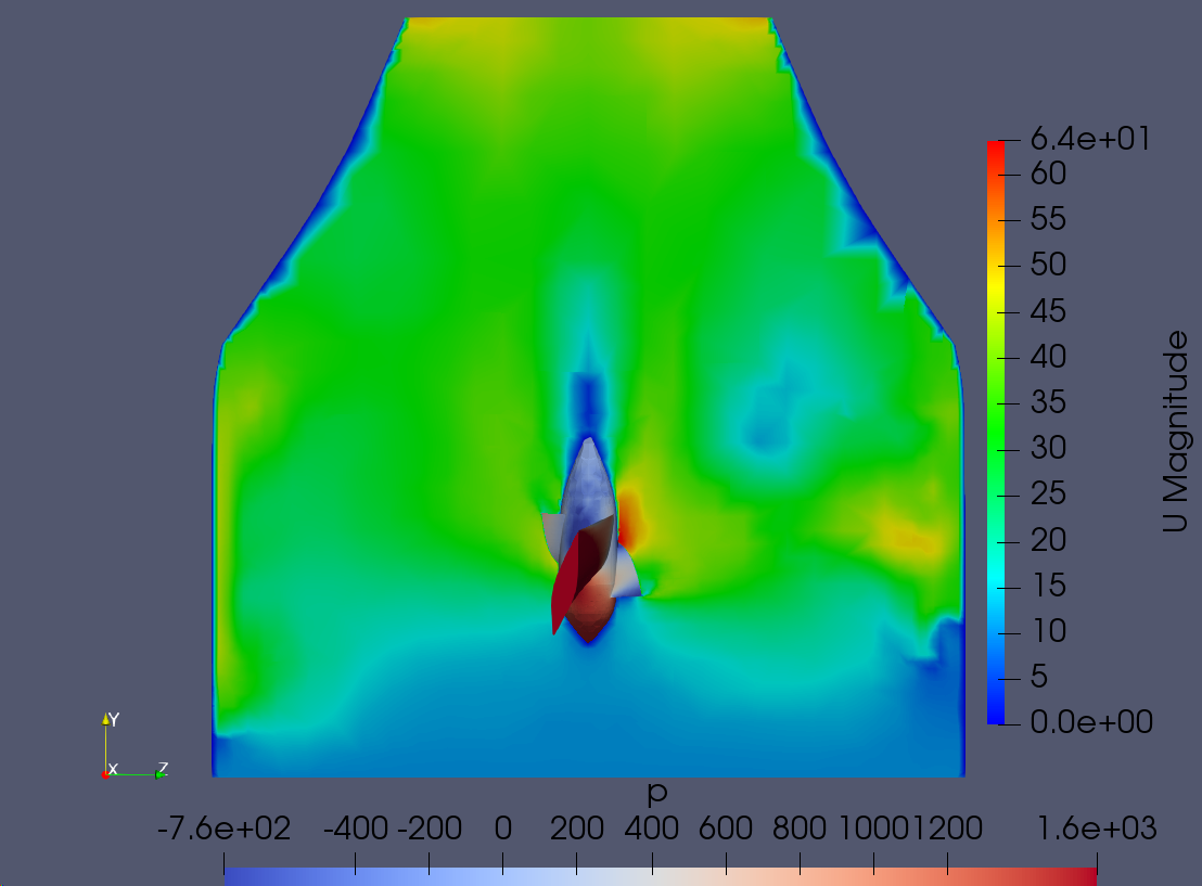
The venturi effect can be seen on top of flow acceleration due to the spinning of the prop.

Streamlines shows the MRF is working.
Everything looks in order and is behaving correctly. You of course will need further refinement in the mesh in order to probably get closer to the results as this mesh is very coarse. Hence my previous question of what the parameters you are comparing to in order to validate this simulation’s results.
2 Likes
I want to measure pressure on the inlet and the outlet and see how much compression ratio I can get. This particular fan design is simply to learn how to set up the simulation. It is literally about make it work and then use the experience to test a more complex design.Thank you for you help @Get_Barried! Can I ask why did you add Result control -> Forces and moments? What does that do? But most importantly, how did you make it work? These last few days of failing to make it work had a toll on my mental health. Would love to know what went wrong so I can move on with my project! Also, why did I get those ‘prop missing material assignment’ errors? How did you fix them?
Hi @glorincz,
Great. That sounds relatively simple. A quick search on how to extract this data offline on ParaView should allow you deduce this.
This is only added to the propeller itself. It is to deduce the forces and moments on the propeller to determine covnergence. As the simulation progresses, checking only the convergence plot is not enough to determine if the simulation has converged or reached a steady-state (where the results do not deviate anymore). As you can see in the convergence plot, it seems like the simulation still needs a little bit more time and that is true if you want to be strict on the residuals criteria. But checking the forces and moments plots you can see that the data is relatively steady after a certain time period which indicates to me that the simulation has indeed reached a steady-state.
Ah yes, CFD does that to you sometimes ![]() . No worries. Let me breakdown what I did different from your setup.
. No worries. Let me breakdown what I did different from your setup.
The first thing I did was to check the geometry. Everything is fine with the exception of the MRF zone. Your MRF zone is like a cylinder with the bottom having some sort of weird bugle and the top containing a cone to keep the center of prop within the zone. From what I can tell, this will not do. The MRF assignment I believe requires a simple cylindrical overlap over the rotating geometry, not something as odd as what you’ve come up with. I took your geometry with the “irregular” MRF zone, deleted it off, made a proper cylindrical solid zone and added it to cover the entire prop. Refer to my project and under geometry to better see what I’m talking about. This fix of the MRF zone seems to be the primary cause as to why your simulation was kind of having problems not only running but meshing.
The MRF zone applies a rotational component to whatever geometry is in the zone. With no geometry, even with the MRF assigned, no rotation of flow will occur. Hence, incorporating the entire prop inside the MRF zone is critical as the entire prop does spin.
Next comes the meshing. I continue to use the automatic mesher you have used that is also set to coarse. The only difference is that I used material point to determine my meshing type (internal vs external). I ensured the material point was within the MRF but not touching the prop at all. This is to tell the solver that my meshing is internal and to avoid any potential problems of meshing the wrong thing. I then assigned surface refinements to the Duct and the Prop with no cellzones as I only wanted the surfaces to be refined. Then I added layers to the prop curved surface only so as to minimize the possibility of low quality or illegal cells which would likely happen should I have selected the entire prop as you did. Lastly, I refined the MRF zone using cellzones and internally. This is critical as the MRF zone requires internal cells to be meshed. Meshed it, checked the logs for illegal cells and layer generation. All is good and I then proceeded to the setup of the simulation itself.
For the simulation setup, it is roughly the same as yours except for some parts. Inlet outlet, no slip wall condition for the duct and prop are identical to yours. I did however, delete off the MRF wall assignment as that would otherwise brick your simulation as it directly contradicts the rotational region assignment.
Since my mesh is so coarse despite having (magically) no illegal cells, higher order schemes (least-squares) was not possible for use. The simulation diverges and crashes. Instead, I switched to standard gauss linear and the smooth solver algo in order to account of the lack of quality in the mesh. Simulation end time was set to default.
As mentioned in the previous post, the simulation converged very nicely despite the coarseness of the mesh. Again, you may need a longer run time should you want to maintain your residuals to be very strict. Post-processed the simulation offline in ParaView to get the screenshots you previously saw and after validation of the physics, deemed that the simulation is complete.
That I am not too sure. If you manage to follow my project setup you should not encounter this issue. For future projects and more complex setups, methodology should be the same.
Hope this helps.
Cheers.
Regards,
Barry
3 Likes