Hello,
I am trying to do Yaw simulations for my car for high yaw angles (10-15 degrees). Now, in order to do that, initially, I used a curved boundary layer and gave sidewalls and upper wall a slip wall condition with the bottom surface as a rotating wall. I gave the inlet and outlet conditions to each wall with velocity on a certain angle of Yaw. You can see the picture below of my BMB
This analysis was done at 5 Degree Yaw. If we back-calculate, for our car, it comes at a turning radius of 9 metres from the COG of the car. I kept my side walls at 2 metres distance from my car, which makes the inner radius of BMB 7 metres and outer radius of 11 metres.
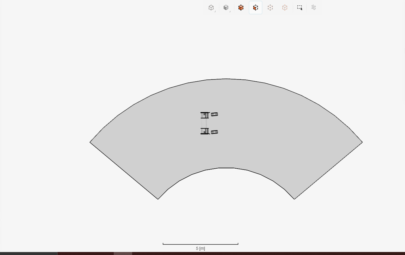
Now, the problem arises when we increase the yaw angle. For 10 degrees yaw, the turning radius comes out to be 3.9 metres from the centre (I know it is not linearly in relation to yaw angles. quite surprising to me). As I mentioned, the bounding box is 2 metres in length from the body on each side. So the BMB becomes really small in terms of length. Is this good enough for doing a simulation? You can see the BMB for 10 degrees as below
Even if this is enough, we cant do sims for 15 degrees as the rotation point would then lie in the bounding box.
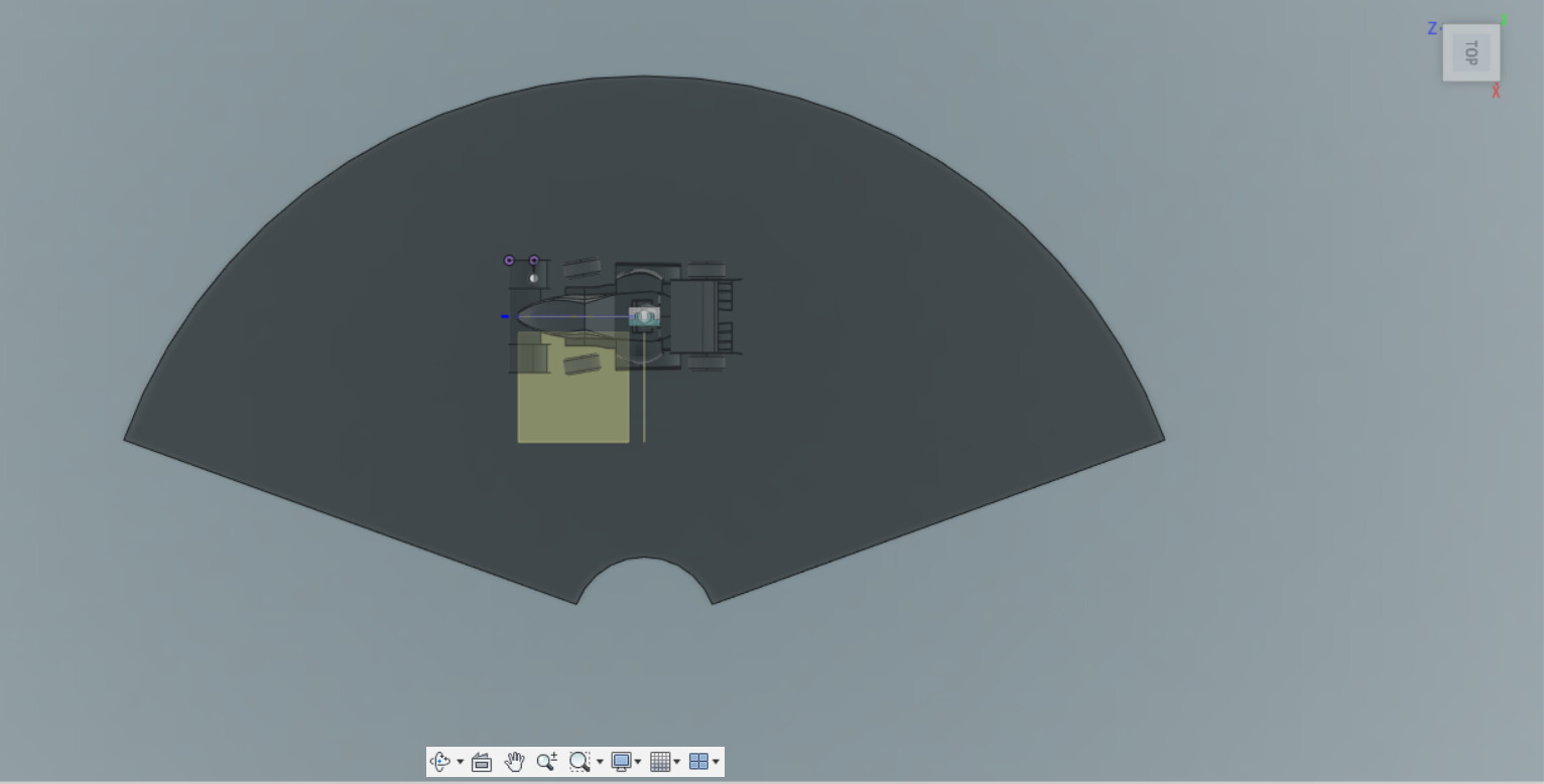
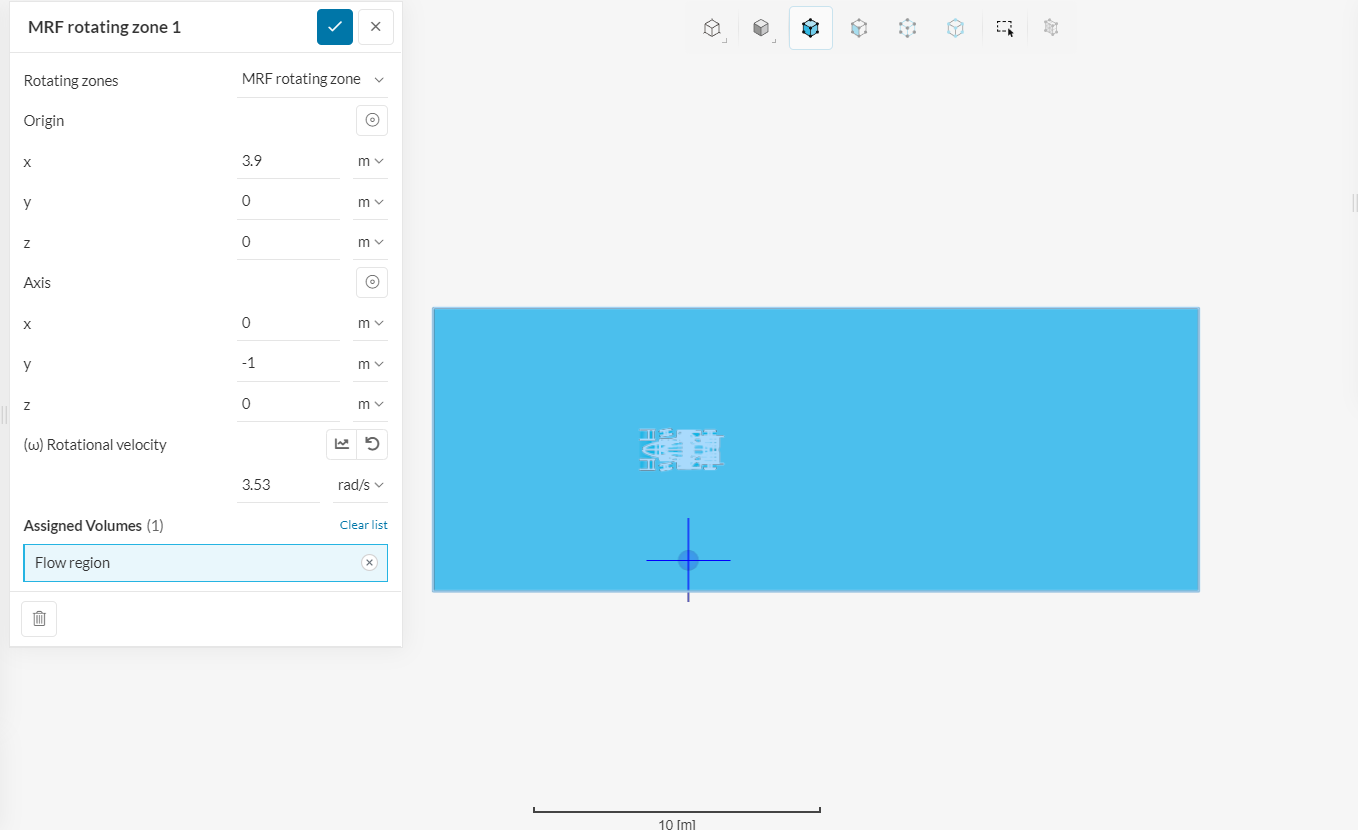
Further, to do simulations properly, I made a normal bounding box and gave all the sidewalls as inlet-outlet conditions from custom boundary conditions, with referral velocity as 0m/s. I gave MRF zone to the whole bounding volume to induce a flow inside the domain. The picture for same can be seen below
The width of the bounding box is 10 metres and I am willing to do 10 degrees yaw which again makes the turning radius from the centre point 3.9 metres. As you can see the problem, the rotation point for MRF lies inside the bounding box. I suspect the simulation would not be able to run.
Finally, my question/s:
Is there a way to simulate higher Yaw angles with curved airflow?
Is the crossflow method as accurate as curved flow? (not rotating the BMB but giving air velocity at certain degrees)
Hi Mihir
Very interesting to see yaw analysis performed on our platform and good work so far.
To 1: The only approach to a small turning radius and high yaw angels would be to further extend the wind tunnel as a straight wind tunnel after the corner.
In regards to that.
To 2: The crosswind methods most of the time are more accurate to small yaw angels since the air velocity difference of the corner inside wheel to corner outside wheel is smaller.
Also, one thing to be considered when simulating such high yaw angels is that the velocity for that case has to be very low, otherwise I would consider the car as drifting. Which such low velocity the static grip of the car is more dominant than the dynamic grip from the aero performance.
I hope that answers a few of your questions.
Best regards Sebastian
Thank you @SBlock for the answers.
On a follow-up question, is the width that I had kept in the curved BMB adequate? FYI, it was 4 meters wide and my car is 1500 mm wide.
Another question that i forgot to mention unfortunately was, is the method that I mentioned here:
Correct? Will the simulation run correctly or will it have problems as the rotation point is inside the BMB
Hi Mihir,
in regards to the question from your post. Your simulation should still work but not converge easily. As the MRF is just applying the rotational velocity around your selected axis. For that, the air will flow in the negative direction on the side that is closer to the border of the BMB.
On the flow-up question. Yes, this might bit a bit tight but I see no other way to do so. Maybe you can extend the wind tunnel to the corner outside more to make sure that at least that side is running as intended.
I had thought of doing something similar at one point. However after some research i found that the increased accuracy was rather low for all the extra work trying to get everything functioning. If you havent found some related articles Here is the info that led me away from attempting this.
You should still try and simulate this though, its really cool if you can get it to work. I also found THIS within simscale. Others have done this type of simulation so maybe there experience will help.
Thank you @SBlock for answering the questions. Seems like the crossflow is the way to go if I want results in a quicker manner than curved flow.
Also thanks to @dschroeder for insight on the accuracy point. Actually, I have read both the articles you have linked in here so thank you for doing that again. I will likely now stick to crossflow as it is easier to simulate for now. But I am willing to go with this curved flow. Sadly, my core hours are about to be exhausted