Hi
my first here was trying to understand an issue i hade while doing my masters research 40 ago.
i was using a plasma source to heat a silicon wafer in a poly CVD system to ~980deg C.
it was sitting on a copper heat transfer plate that was in contact with a large 50 deg cold plate.
the copper heat transfer plate had a shalow ‘skirt’ and only the bottom of this skirt was touching the cold plate.
at the time, i was expecting the copper heat transfer plate to curve by few millimiters because of the temperature difference and the thermal expansion. but, the poly growth rate which is temperature dependent was pretty uniform!
after the simulation, i found that the center of the heat transfer plate was almost the same temperature at both top and bottom, withh most of the heat flowing to the cool plate via the ‘skirt’.
when vieing the results, the vector map made sense and was of concentric symmetry.
the color map however, when view from the top shows that the plate is bending around a lateral axis…
i tried to change the support but it remained the same.
as i’m new to this furum, i appologize if this was too long.
@ggiraldof
Hi @shaykaplan
Thanks for posting in your issue in the forum, and please receive a warm welcome!
Very interesting project that you have here. I will suggest you to make these changes to improve the simulation:
-
Refine the mesh. Ideally it should have at least two elements across the thin walled parts, and the more the better to capture the temperature gradient. You can control this using manual mesh sizing and specifying the maximum edge length to be half the thickness or less.
-
If you are looking at the color map for Z displacement, you will see a gradient corresponding to one horizontal component of the axis symmetry. Please visualize using ‘All displacement’ which is the vector magnitude. Also, notice that the vertical direction in your model is Y, in the case you want to check the deflection in that direction.
-
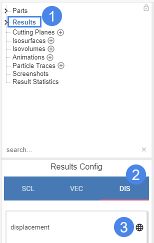
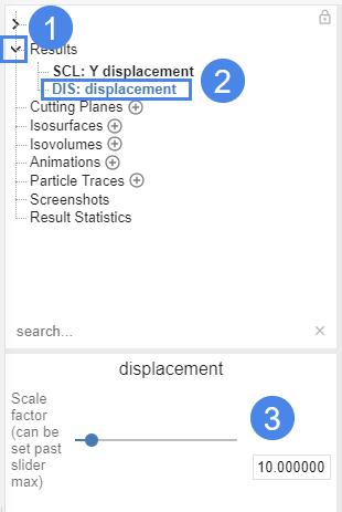
You can visualize the deformed shape by going to Results - DIS - displacement, click on the globe icon. You will notice a mainly radial expansion, but if you increase the deformation scale, yo can notice some deflection also.
Please review those and let me know if they clear your doubts.
thanks a lot.
i got better! and the simulation much better
still couldn’t find how to change the deformation scale…