The aim of the study is to study how the dispersion is affected by the shock absorving system and a muzzle restraint design.
Initially a full geometry of the phalanx CIWS was modeled using Siemens NX. The total actual mass of the system is about 6,5 tons. Though after importing the 3D model form NX to Simscale the overall mass of the system appeared to be 90 tons. Overweight. The explanation (perhaps) is that the modeled parts are continuous solids. To tackle this issue, only the components that are actually solid in reality were kept, the rest of the components were modeled as point masses. I would like some explanations on the following :
- Do the point masses transfer load in simulation and what is the difference between a point mass and an actual 3D modeled part ? A point mass is not that Core hours intensive but is it a trustworthy way to bypass a geometry , especially when tackling overweight issues ?
- The point masses menu just asks center of gravity and mass, i am wondering why no element properties are not asked.
- Supposing point masses boundary condition modeling are not adviced , is there any way of changing the actual 3D geometry mass distribution ( almost every model must be 10 times lighter)
- We study the dispersion issue in 3 angles of firing (0 degrees, -25 degrees and +85 degrees), the question is , does the center of mass of the components modeled as point masses change when they are angled or they remain the same.
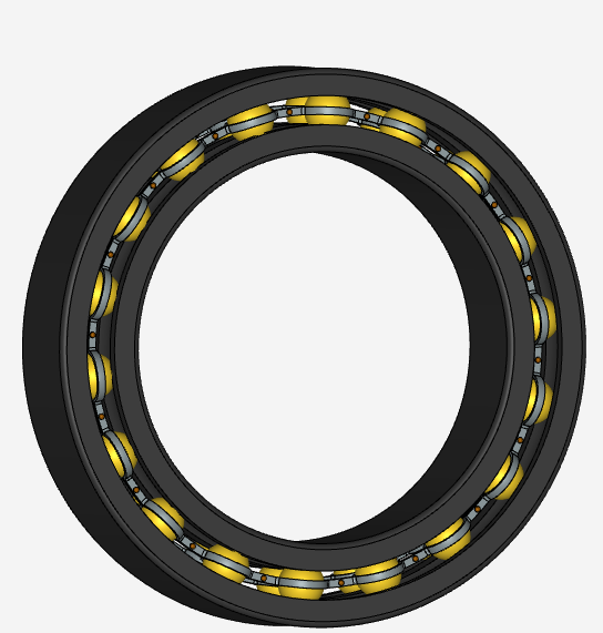
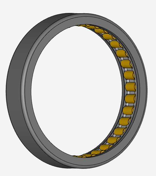
- Bearing play a crucial role in gun dynamics, although a detailed 3D geometry is modeled, for simulation issues (crashing simulation - high detail) alternatives of the actual geometry are considered.
i) The balls of the double row ball bearing are simulated as elastic support boundary condition. In this case the the bearing will hold the rotor with virtual springs so the gun will not be able to rotate. The advantage is that rigid body motion problem will be solved , though the gun rotates in reality in either 500 and 750 RPM. Also, is there any built in option in Simscale to measure the actual stiffness that the bearing would have in the model ?
ii) Another option is that the bearing would be modeled as a point mass with the corresponding mass and center of mass. This option is the easiest though doubts of trustworthy modeling occur (does the point mass carry radial and axial load, does it behave the same as an elastic support? - The whole system is mounted in 4 corners where the shock hydraulic system is established. An elastic support boundary condition will model the absorbers, the question is whether the elastic support will be modeled as isotropic or orthtropic. The absorbers get displaced axially downwards only during operation only *the rest of degree of freedom must be locked).
- Overall, only the barrel tip displacement maters and how it is affected on the initial truss and the extended truss , when the weapon fires in 3 angles. Which tool / option from the menu gives the information of the barrel tip displacement to get the comparison. Frequency and Harmonic analysis will be conducted, do you have any simulation algorithm to suggest?
Below there is a link to the project topic - full overweight
Below there is a link to the project topic - simplified geometry
Below the screenshots of the bearing which hold the rotor shaft (either elastic support or point mass is considered instead of the actual geometry)