It has been stated that a direct import of the flow region is possible, but SimScale only seems to permit selection of (or generation of) a flow region as the inverse of a boundary (internal or external). Can anyone advise what the steps would be to select an entity as the flow region? If that is not possible, I will have to artificially create a simplified boundary model (too intensive to import existing final parts with requiring significant clean-up).
Thanks,
z
Hello!
That is correct - it’s possible to import a flow region to SimScale directly from your CAD software. If I understood the question correctly, it sounds like you are trying to run a flow volume extraction in CAD mode after importing the flow region?
If that’s the case, when you import a flow region to SimScale you won’t need to run a flow volume extraction operation again. Here are the two possible workflows:
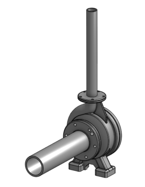
Workflow number 1: importing a CAD model containing the solid parts to SimScale and generating the flow region locally. We’d import something like this to SimScale:
This geometry contains only the solids and no flow region. In CAD mode, you would need to use an internal flow volume to generate the flow region, and then you would delete the solid parts from the CAD with a delete body operation.
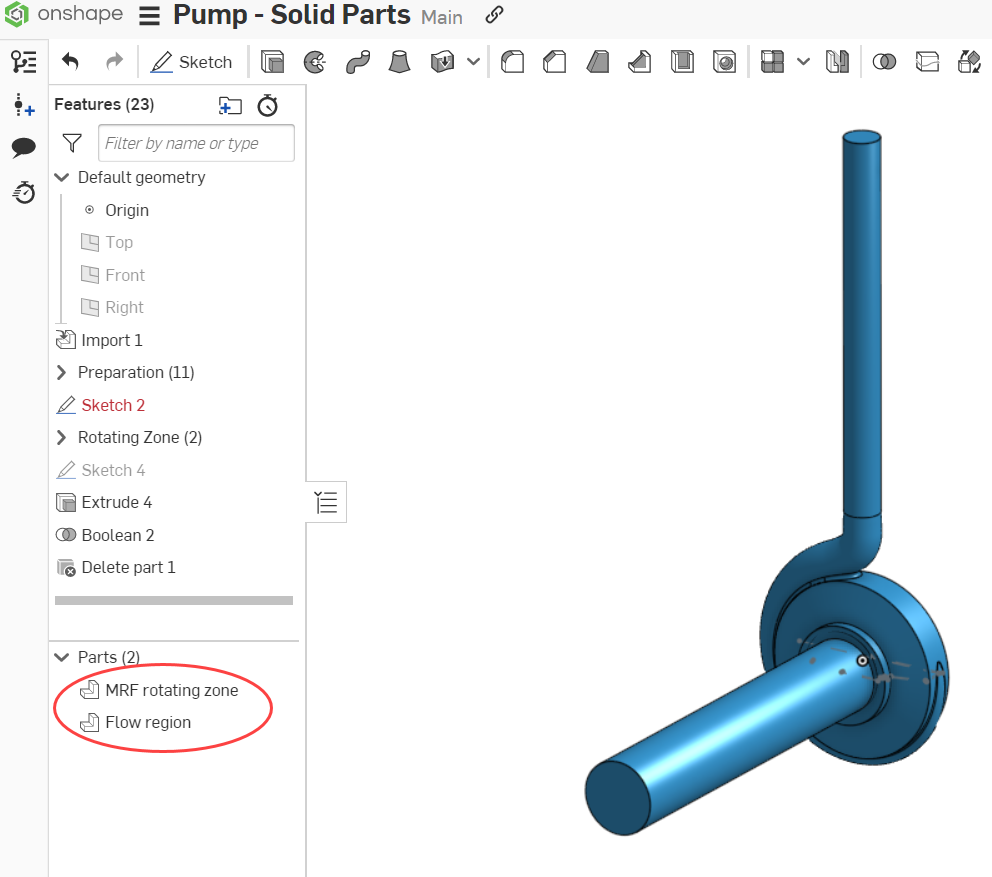
The second workflow, which is the one you are interested in, involves generating the flow region directly in the CAD tool and importing it to SimScale. With this alternative approach, you would import a CAD model that looks like this:
Then you can proceed to create a new simulation directly. There’s no need to enter CAD mode at all (or generate a new flow volume), since the CAD model already consists of the fluid domain.
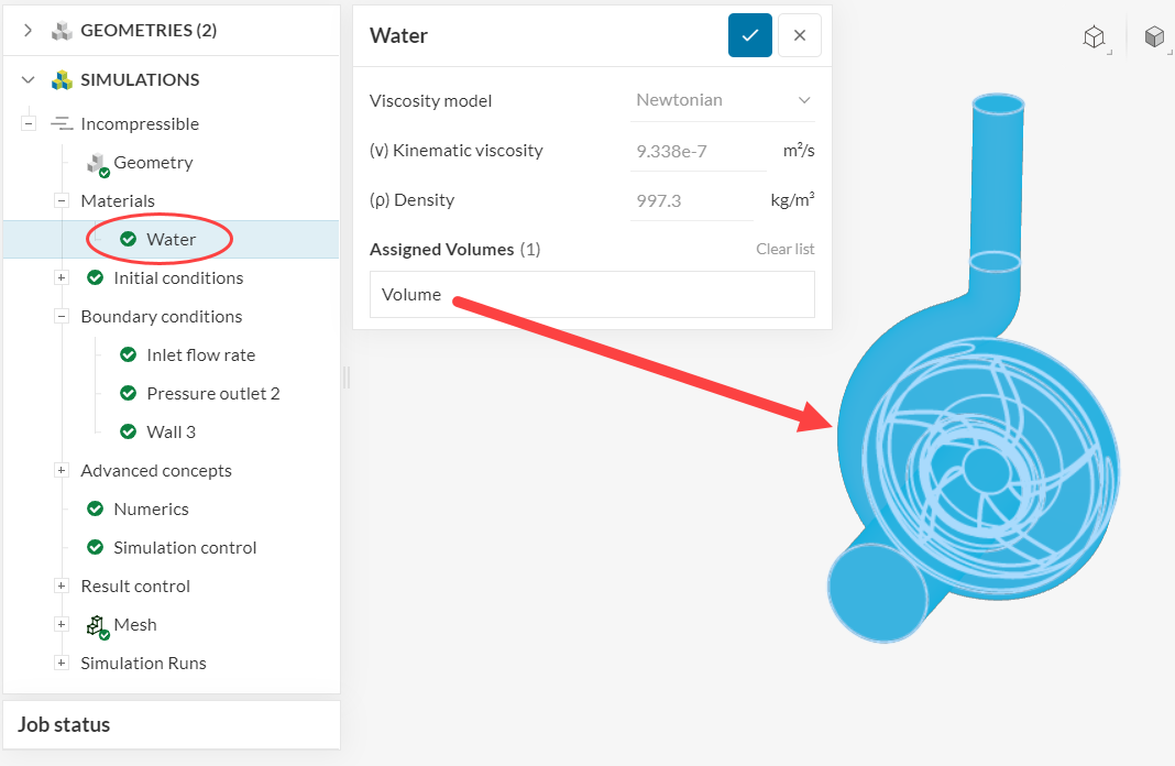
With either workflow, you can assign a material to the flow region by creating a new material and clicking on the volume of interest:
If it’s still unclear, please let us know!
Cheers
1 Like
Thanks Ricardo - I had selected the appropriate solid body for the “Material” as you had indicated. What seemed confusing I guess is from a demonstration using the “1st workflow” where the rotating zone was “excluded” from the flow region and then the impeller (a yet 3rd solid) was deleted afterwards. In trying to follow the 1st workflow methodology but via the 2nd workflow, I imported all three bodies into the project. Does that make sense?
Hi @MdM2022cfd ,
That should be possible to do. Here is how the workflow would look like:
-
The first step is to have all 3 volumes (flow region + impeller + rotating zone) in the same CAD model. This can be done in CAD mode by using the “Add CAD” operation:

-
Note that the added parts maintain the same size and positioning as they had when you imported them. So make sure all parts are in the correct position in your CAD tool when they are exported.
-
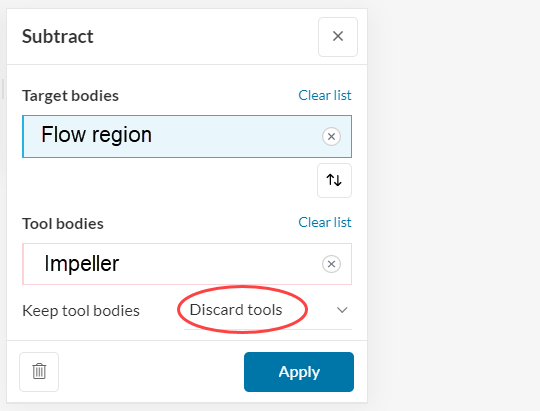
Once all volumes are in the same CAD, you can run a “Boolean” > “Subtract” operation, with a configuration like the one below:
By discarding the tools in this operation, you will automatically delete the impeller. In the aftermath, you will have a geometry containing 2 volumes: the flow region and the rotating zone. This is the configuration that should be used for the simulation.
Cheers