Dear SimScalers,
in this weeks spotlight we are having a look at a FEA simulation of a Differential Mount by RUB Motorsport - the FSAE team of Ruhr-University Bochum in Germany (Submission of the project by @steinccf).

\underline{\textbf{Introduction & Problem specification}}
Since 2016 the RUB Motorsport team is using a 1-cylinder engine. The main drawback is the enhanced engine vibration and that the old differential mount was fixed to the frame and broke. They clearly underestimated the effect of the vibration.
In 2017 they used an entirely new design similar to what we present in this Project Spotlight here. It holds the engine and differential in a decoupled system which is damped by rubber mounts. The method for the FE analysis was to make a static model and design the part for a minimum safety of 4.5. Brutally inaccurate in @steinccf 's opinion but the part did not break! The goal this year was to reduce the weight since the solution of last year was pretty heavy (see safety factor). A more accurate FE analysis was needed to also save some weight!
The spotlight is divided into the following parts:
-
Geometry
-
Meshing
-
Simulation
-
Simulation with SimScale
-
Results & Conclusion
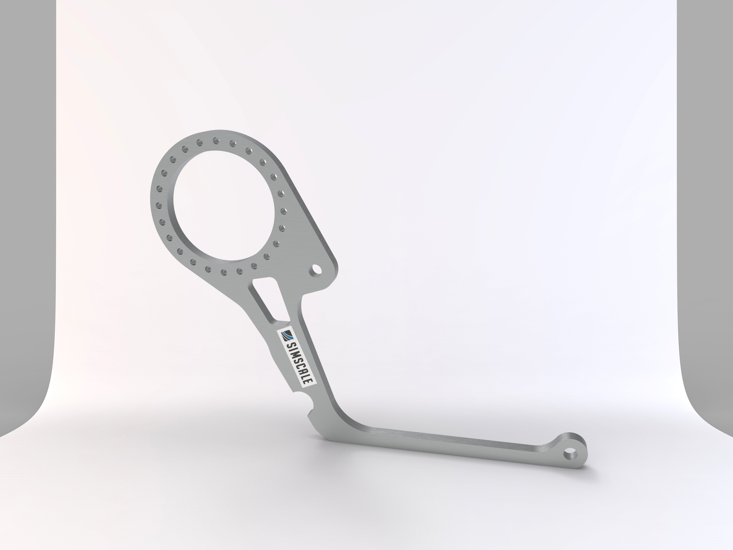
\underline{\textbf{Geometry}}
Format: STEP (Rendered with KeyShot)
\underline{\textbf{Meshing}}
Type: Tet-Dominant Mesh (A fine mesh was chosen!)
\underline{\textbf{Simulation}}
Type: Static Analysis - Advanced
The dynamic forces were modeled with a simple sinus function and the simulation interval and timesteps were chosen so that one point will hit the maximum of all sinus functions. This is to ensure that the worst case is included in the simulation. All other values were put in according to the data input.
There are 4 iterations of this simulation with geometry optimization after every FE analysis.
\underline{\textbf{Simulation Details}}
\underline{\textbf{Material}}
The aluminum alloy the team is using (7075-T651) has a fatigue strength of 159 MPa, an elasticity modulus of 71 GPa and a poisson ration of 0.32.
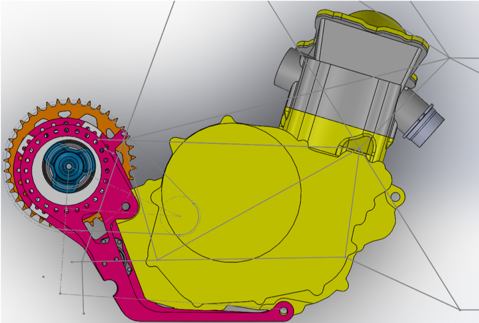
\underline{\textbf{Boundary Conditions}}
The engine vibration was simplified to one direction and the acceleration data was sourced from a similar sized 1-cylinder engine. They planned to do acceleration measurements of the engine setup this year which was not possible so far. The movement of 4 mm was calculated from the sinus-function of the acceleration data.
The boundary conditions were sourced from the datasheet of the dampening mount and the forces applied to the differential at full load.
There are a couple factors that are not considered in this to make the simulation easier. Gravity, cornering acceleration and acceleration from driving over bumps would be examples of this. They would require a multibody simulation of the engine and a drivetrain.
\underline{\textbf{Solution}}
Machine cores: 32
\underline{\textbf{Numerics}}
Equation solver: MUMPS
\underline{\textbf{Results & Conclusion}}
\underline{\textbf{Iteration1}}
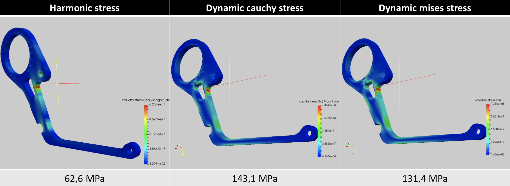
Figure 1: This iteration was not considered to be used in the future
\underline{\textbf{Iteration2}}
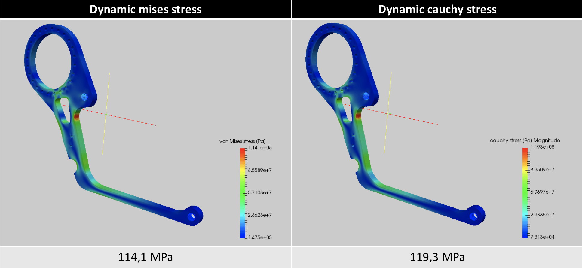
Figure 2: This iteration involved a 11mm reduction in thickness
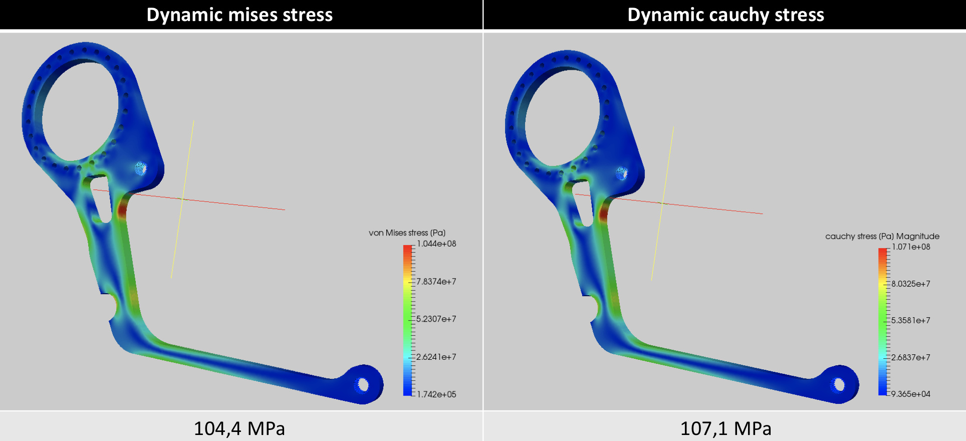
\underline{\textbf{Iteration3}}
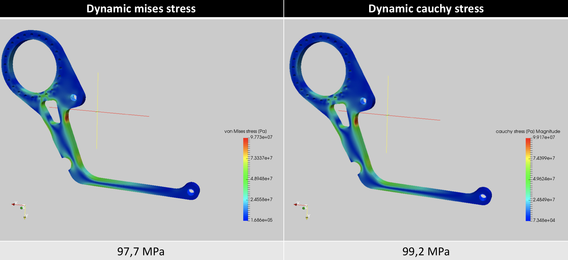
Figure 3: Optimization of the geometry involved
\underline{\textbf{Iteration4}}

According to @steinccf the next step is a topology optimization which would have been nice but because of the dynamic nature of the problem it is more efficient to do it manually. They hope to do a much more precise simulation for the year.
\underline{\textbf{SimScale Project}}
To look at the simulation setup, please have a look at the project from @steinccf :
Differential Mount right 4th Iteration
To copy this project into your workspace, simply follow the instruction given in the picture below.

\underline{\textbf{Visit our SimWiki by clicking on the picture}}