I changed the inlet velocity to 0,0976 m/s to get a volume flow of 0,23 m³/s.
Booth simulations run with the same Mesh and the same settings except the end time and the wirte intervall.
Run 5; 10 s sim. duration; 0,5 write intervall
Run 6; 5 s sim. duration; 0,25 write intervall
In Run 5 there is some kind of an error at 3.5 seconds, all of a sudden the water is everywhere in the geometry.
In Run 6 the simulation runs straight without any errors to 5 seconds.
Here is a Video:
I can’t explain the behavior. If it were in both runs, I would say that it is due to the missing y+ layer. I have to calculate and add this layer. Why does the model calculate once only up to 3.5 seconds and once up to 5 seconds, with the same settings ?
My experience is that the this is not unusual in the CADA (Computer Aided Design Analysis) world…
I have been told that it is likely that two runs can have different results, due to purposeful randomization in the algorithms that decide which cells each core calculates. That is not the precise way to describe the issue, but that is the gist of it…
The issue is because you have a zeroGradient boundary at the outlet for alpha.phase1. When a water droplet exits the domain, the solver will assign that cell an alpha value > 0, meaning that there’s some water there. That would not be a problem if all the flow is exiting the domain. The issues arises in case you have reversed flow of air—water is much denser and droplets can go against the air stream—, which is very likely in this case. What happens is that because the solver assigned that cell a value > 0, so, now the inflow of air suddenly turns into water and it goes nuts from then on.
So, now that we’ve identified a problem, it’s time for a solution. And the solution to that is to use inletOutlet boundary condition for alpha.phase1 at the outlet with inletValue 0. With this, you get a zero gradient boundary for outbound flow, and in case there’s any reversed flow, it will have alpha.phase1 = 0, meaning that there won’t be any water entering the domain through the outlet.
I did several runs with a 2D model last week, trying different boundary conditions, and found that the best combination for the outlet is something like this:
alpha.phase1: inletOutlet (inletValue 0)
U: pressureInletOutletVelocity or inletOutlet (inletValue vector pointing out of the domain with a value similar to that of the flow)
p_rgh: totalPressure (value 0)
Let me know if this helps.
As for why one simulation runs ok and the other crashes… I don’t know for sure; but because you have adjustable time step on, it could be that one of the runs just didn’t release that fatal droplet just jet. But it would crash as well at some point.
So, i ran three simualtions and all finished up :), it looks like the bc from @pfernandez works !
Again, thank you for your boundary tests.
Here are the videos:
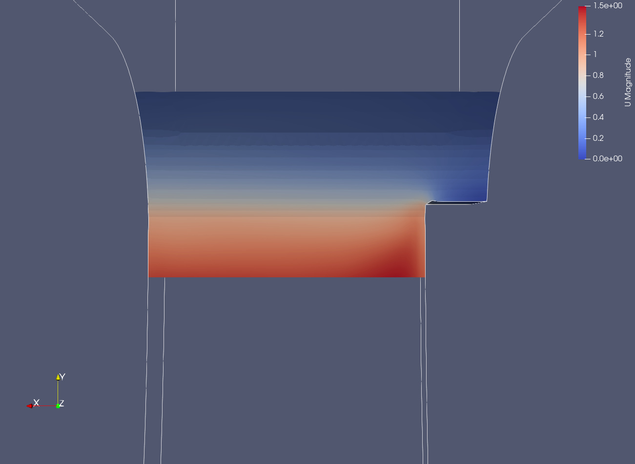
Run 10 0,0976 m/s inlet 15 seconds duration
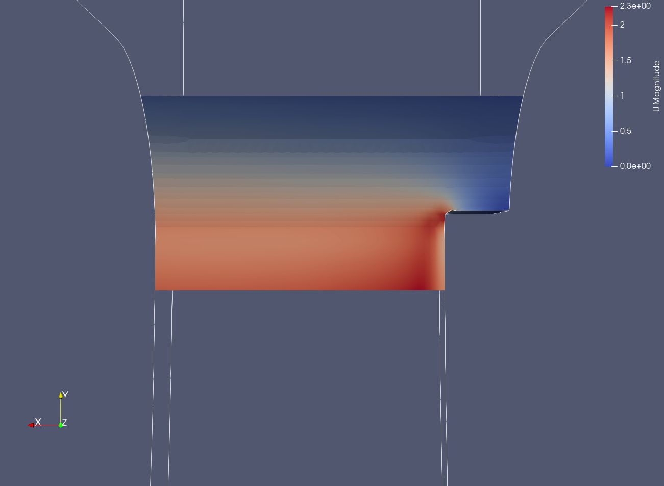
Run 11 0,5 m/s inlet 15 seconds duration
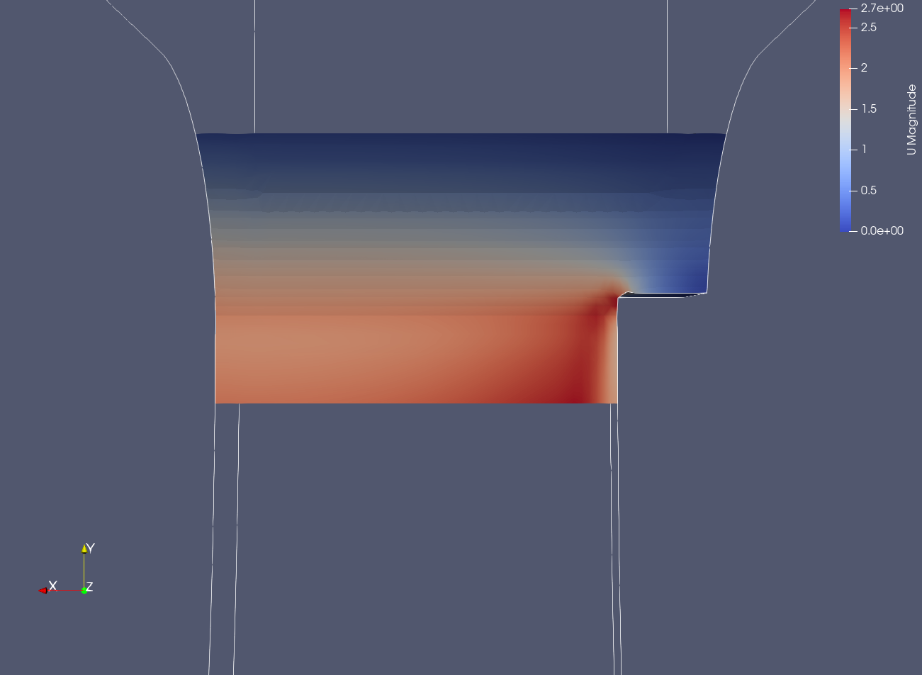
Run 12 0,7679 m/s inlet 15 seconds duration
I think, the next step is to add the right Y+ Mesh size. I didn’t do it beofre, and have a few question about the basisvalues.
I looked into different topics who deal with the Y+ topic.
To calculate the right mesh size, i need the freestream velocity, and the boundary layer length.
In my simulations, the velocity is increasing with the gradient of the arch, so i can’t quote a fix velocity.
The beginning piece of the arch is responsible for the preformance, i think.
So my idea is, to take the “freestream” velocity from this spot.
As the boundary layer lenght, i take the lenght of the arch, it’s about 5,2 m.
So my questions:
A: Is it possible to take this values, like i do, or is it completly wrong ?
B: Of corse, i get different velocitys at this point, depending on the flux at the inlet.
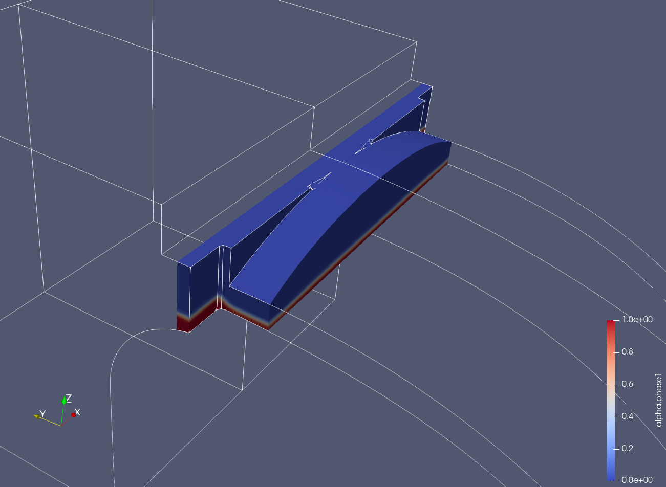
Below, three pictures from the simulation runs mentioned above.
All seen from underneath the arch, and taken in the last second of the simulation.
Run 10: