Hello,
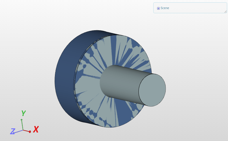
I am trying to mesh the flow region within a centrifugal impeller. It seems that I cannot define the correct location of the material point such that I obtain the flow region within the faces of the geometry. I have included a cylinder to define my rotating zone for the future boundary condition. My inlet is a solid cylinder. Both of these cylinders where added to the original CAD file prior to uploading. Any help would be greatly appreciated.
Thank you,
Fabian
Hi Fabian (@falvarado)!
Is it somehow possible for you to get rid of the volume-intersection/self-intersection in your model first? Uploading a new, modified CAD model should work then.
Let me know how things go!
Cheers,
Jousef
Hey Jousef,
Are you referring to the cylinder imposed onto the impeller for the MRF zone definition?
Thank you,
Fabian
@jousefm if this is the case, then how would I define the MRF rotating zone?
Hi @falvarado,
I am referring to the “penetration” (if you want to call it like that) that can be seen in the picture posted by me. Is there a way that you can get rid of this?
Regarding the MRF I can recommend the following resources to you:
Let me know how things go 
Best,
Jousef
Hi @jousefm ,
Thank you for your direction. I will look into those resources and keep you posted.
Best,
Fabian