I am simulating an axial pump, and I would like to know the torque required. I have done a Forces and Moments under Results Control on all of the surfaces of ONE of the rotor blades. The rotor is aligned to the y axis. Will the total torque on that rotor blade be the hypotenuse of the right triangle created by the “pressure moment x” and the “pressure moment z” as the legs of the triangle? If not, what is the torque?
Thank you.
Hi!
The torque is the action that creates rotation of the parts around the given axis.
The pressure moments in x and z directions are reported as acting in the center of rotation, and the torque compensates for the translation of the forces. Thus, the calculation you outline is not quite correct.
Instead, you would need to take the resultant force vector at each cell in the surface and use the cross product with a radius vector from the rotation axis. Then, you can project the moment to the axis with the dot product.
Hi IronManDylan,
That is an awesome mathematical answer from @ggiraldof , sadly after 35 years I’ve forgotten most of my university maths 
Here is what I’ve been doing…and some of the answer to the question…
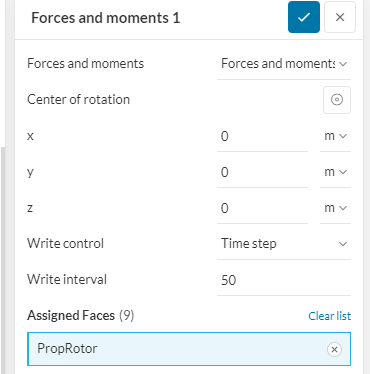
I take a little simpler approach I locate the center of the rotor at 0,0,0
I then use the Results control and assign the total rotor object, in my case PropRotor
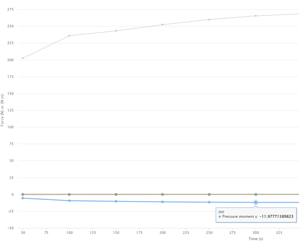
Then all I have to do is read of the Pressure torque for the total rotor torque.
For me, I read off the Pressure moment (N.m) for Y axis, as this my central rotational axis for the rotor.
Then I suppose if you wish to determine the torque for each blade, then get the total torque, divide by the number of blades.
Then how do you determine the force acting on each blade? I don’t know, as you would need to know the position of where the force is acting on the blade and determine the ‘lever arm’ length and then the force on each blade would be equal to the Blade Moment/Lever Arm in the x & z directions.
You could determine the vertical position of where the force acts on each blade, by moving the rotor down or up, until Mz or Mx turns to zero. Then maybe there are simple simultaneous equations that can be formulated to solve the lever arm, given you know the moments. Or, do you move the rotor up and down until Mx = 0, & note this position, then move the rotor up/down to get Mz = 0 , to get the Lever A rm distance, then you have two distances that should intersect at the point of where the resultant force is acting on the blade, but then I don’t know the angle applied by the resultant, but this may not be important.
Sorry I couldn’t provide a total answer.
Kind regards
Ted
1 Like