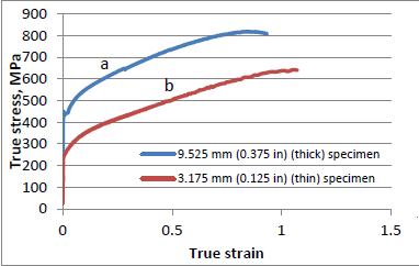
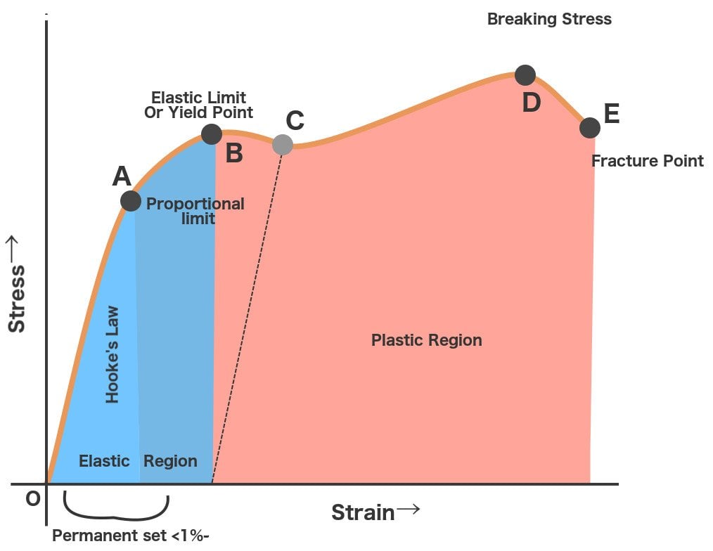
I would like to measure volumetric Von-Mises stress and stress-strain relation (like THIS).
So I used the Dynamic analysis solver to it as the stress is time-dependent.
Did I approach this problem of mine correctly with the following simulation configuration?:
[Simulation Case]
It always gives me an error. However setting up was too easy to be true to work. :S So maybe I made a few mistakes. Could you elaborate what can be setting up in order to work properly?
The CAD file I made with FreeCAD has been converted to a Solid Body and fixed all the nodes.
Having had a look at your model, the 1 issue I have found with your setup is that you have set your entire part volume as a fixed value condition. You don’t explain exactly what you are trying to model but I imagine you will want 1, perhaps 2 fixed surfaces. You can use fixed support instead of fixed value as a fixed value with the values set to 0 is a fixed support. Next time if you get an error, don’t delete the simulation run as the error and log can help us understand what went wrong.
Having just reread your post, it seems that you understood that you fixed your entire model. Perhaps tell us what you were trying to achieve by doing this and what is the scenario you are trying to model.
I just noticed a problem with your material settings. You said you wanted to model the post elastic stress strain behavior such as that shown in the graph you linked. That means that under your steel material you should change material behavior to plastic and choose a creep formulation such as strain hardening. You will then be prompted to fill in additional properties. The following two links will be useful;
Note that I actually tried to run your model for you and the simulation was aborted due to lack of memory so you should reduce your number of iterations and if necessary your mesh density so that you can run this case
Thanks for the help. Yeah, I will leaf through the documentation more precisely, I made a few mistakes, not pro in SimScale yet.
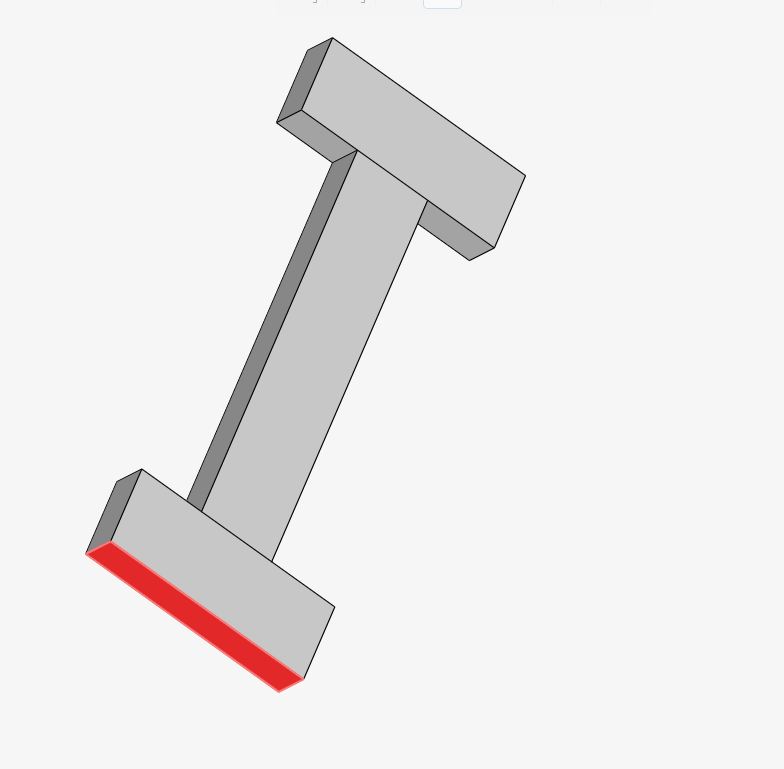
The problem I would like to simulate is like what a tensile-test machine could do with a certain material (mainly steel): applying uniaxial, equal force on both end of the H-shaped object.
This force would be a time-dependent value so it is increasing with every second. Then measure the Stress-Strain diagram, which is similar to that one in your link. Also would like to measure the Von Mises stress visually in the volume, and then create coloured volume layers in the post-processing stage.
In that case set 1 surface as the force and the opposite surface as fixed. Regarding you wanting to simulate a gradual increase of stress, that will make it harder for you to keep within memory allocation. By all means give it a try but you may have to settle for simulating several different constant stresses in seperate simulations.
Here is [updated] version of the aformentioned simulation, still giving an error. The solver log for me only readable in French, but i do not know why is that. So it is very hard to see through it, what went wrong.
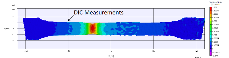
For clarity, I would like to have diagrams similar to these:
Where is the graph from? I can not see any completed simulation runs in your project and this result does not seem consistent with the scenario you are trying to setup.
I noticed you have now set the material to include plastic region and creep and that you have improved your boundary conditions. Two points I have noticed;
You changed the default modulus of ABS and its way too high now (more like that of steel), did you mean to do this?
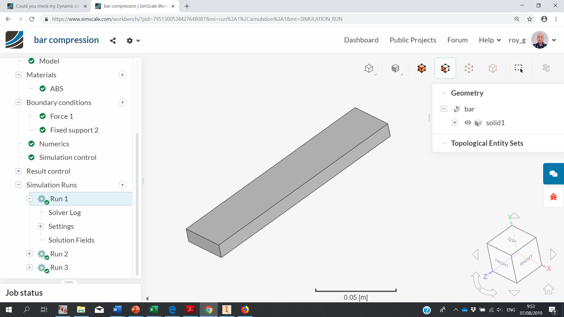
If you want to simulate axial compression of a bar you only need to model the bar itself. Perhaps in a lab test you will use the H geometry so you can grip it better, but not in a simulation. So change the model to a bar and then define one surface as fixed and the opposite surface as having an axial force.
Yeah, it was intended as I would like to do the measurements on steel. The graph is from an article, where uniaxial stress test was measured. I would like to do something like these graphically, could it be done with SC?
So only a steel bar I need, then set the vertical surfaces - facing towards each other - as force & fixed support?
HI @znovak
I would like to suggest you change b.c. applied face. in this case, you can apply force to the only bottom surface of your part and try to simulate.
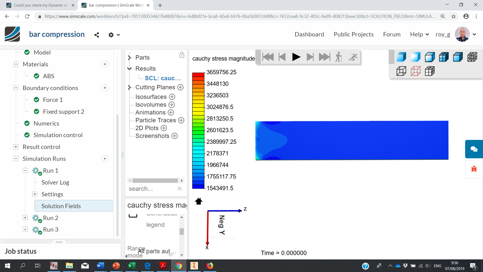
I ran the simulation for you and unsurprisingly the stress is quite constant throughout so i’m not sure what your 2D heatmap is showing. Project link below but note this is a static study as I did not want to use too many core hours and run 3 is for a different boundary condition (cantilever beam stress)
I saw the simulation, but we misunderstand each other I think. It will be not a compression project on my behalf, but a strain analysis as there are two forces on both end of the object. Each force will be the opposite direction pointing outwards from the object, but their magnitudes are equal. In this case, the von Mises stress map should be similar to those on the 2nd picture I linked. Basically, it is an uniaxial stress test.
