Could you please help us in creating the curved mesh as per the mesh in the above shared link?
We were facing problem in creating a curved domain in Simscale. Is there any method where we can make the curved domain and mesh it, both in Simscale without using other softwares like OpenFOAM for meshing.
It would really benfit our team in further simulations for testing our aero package in cornering conditions.
Or
Is there any other alternative method for doing simulations for cornering conditions?
Can you try meshing it in simscale rather than importing the mesh so that way we can see the mesh log. Having said that, what makes you think you have an error with your mesh?
What are you trying to simulate? From what I see, your mesh is probably unnecessarily fine and and for some reason it gets even finer towards the middle. Do you really need such a fine mesh?
The main problem I see is that you have not stated a value for your inlet velocity. You may also want to set your outlet to pressure outlet. Tell us more about your simulation so that we can help you more.
I see you have set some walls to slip boundary and others to non-slip which may or may not be correct depending on what you are trying to model.
@roy_g
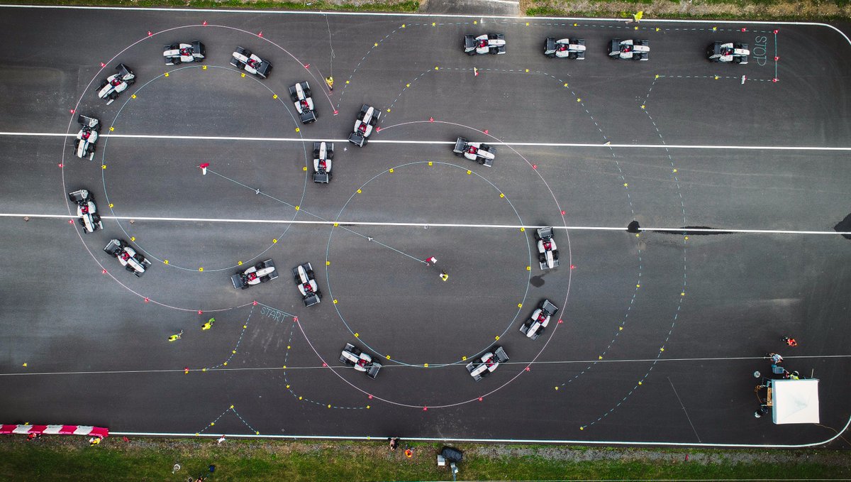
I think they are going to simulate the aerodynamics of Formula student car while performing skid pad test having car model in the middle of the fluid domain having finer mesh.
I am pretty sure that forcing your air around that domain would not achieve the results you want (ie you want stationary air hitting a car moving through it on a curved path).
Perhaps there may be a way with putting your car in a rotating zone (perhaps closer to reality), not sure if that has been tried before…
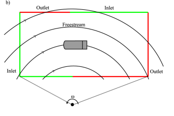
@DaleKramer, you are right modeling this kind of simulation with stationary air is not a good go. There must be a valid inlet velocity. The following figure shows the two techniques to model cornering aerodynamics of vehicle taken from the following research paper published by SAE.
https://pdfs.semanticscholar.org/0a6f/8e769f8c867509f7bcaa22aa021b5a5f9832.pdf

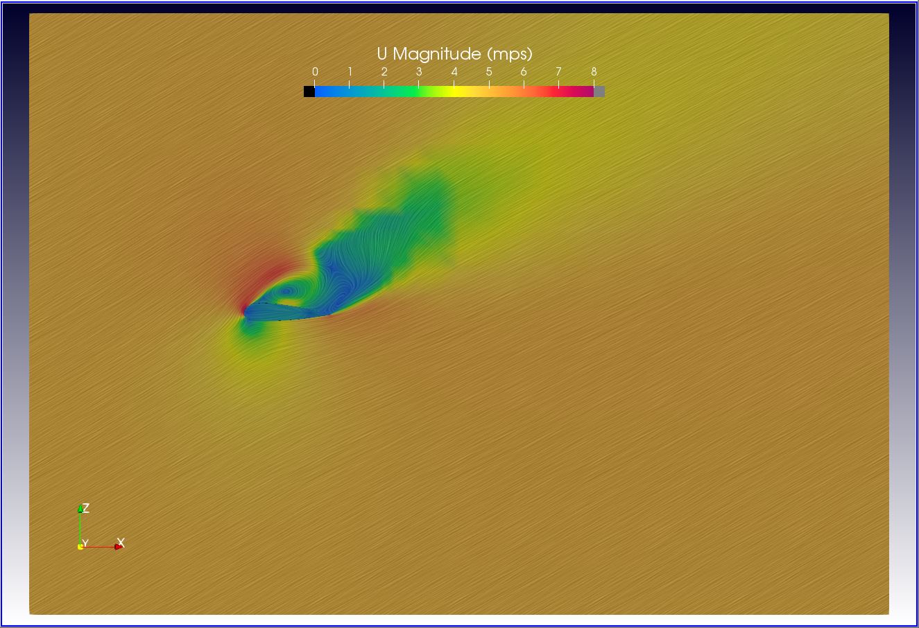
Cool, in any case I would set it up with no car in there and run a sim, export data, slice the results and view with ‘Surface LIC’ in ParaView, like this (but take out your car and in my case I would have taken out my 30 degree AoA paraglider wing at 5 mps inlet).
With this, it is easy to visualize that you have the flow you want in your domain ![]()
Have a look at the particle trace from the link provided by @adynamics
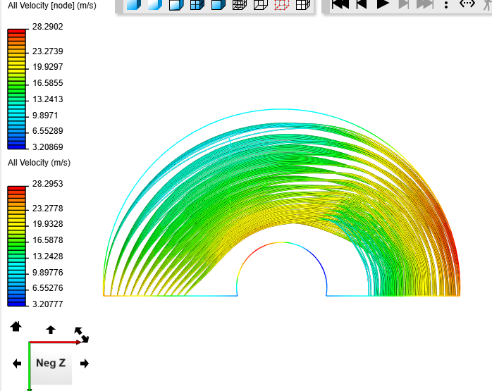
That is what my brian suspected, not ideal…
There are some good input ideas in the forum about cornering in aerodynamics, just use the search function.
What you can do is to upload the CAD already in a curved manner with the vehicle inside or you use the midpoint of the geometry as an anchor for rotation.
Cheers,
Jousef
How can we give two boundary conditions to one face of boundary box?(inlet and outlet to one face)
Custom>Inlet-outlet and Custom>Outlet-inlet BCs essentially do that but you can only assign air to go in OR out of them.
You have to create the bounding box and split the face of the bounding box in CAD model as per required.
Thanks. One more thing, what should be the direction of velocity inlet at all the places?
But can i give two boundary condition to one face?
No, I do not think so.
We used to be able to assign a Symmetry BC and a Wall BC to one face but not any more 
The question is why do you want to?
You are confusing Faces with Faces that appear to be Planar in that case.
You are showing a cross section of a 3D object there. Each green or red line segment represents a line on the surface of a face that ran from one face edge to another edge on that face…
NOTE: Faces do not need to be Planar in SimScales definition of Faces…
Once you have those faces set up correctly in your CAD (those faces would become a CAD defined ‘sort of’ Background Mesh Box (BMB), that would be run as an internal mesh in SimScale), you still need to get that air flowing in a curved path.
I believe that may be accomplished by putting an MRF rotation zone cylinder in your CAD file with an axis that runs vertically up from your screen and with a radius that encloses all the faces of your CAD BMB. Then, in SimScale assign the properties of that MRF under ‘Advanced Concepts’.
I have never set a simulation up like that but that is how I envision that it may be done.