Hello,
I want to model the airflow of a small server room using a “convective heat transfer” simulation.
To model the server racks, I am trying to use the “Darcy-Forchheimer medium” tool. I am aware that the official simscale demo about data center modelling (https://www.youtube.com/watch?v=HJHbX2rQVik) uses a different approach. My goal is to reduce the mesh size needed.
In the following illustration you can see exactly what I have set up in each rack of the room:

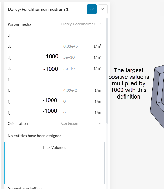
The porous media coefficients used are the following:
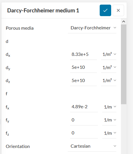
- The coefficients in the X axis (where the air should flow) were taken from http://etheses.whiterose.ac.uk/4567/1/Ali%20Almoli%20-%20thesis.pdf
- The coefficients in the Y and Z axis were invented by me attempting to prevent the air from taking that direction.
My first question is whether this combination of conditions (like putting a heat source and a porous media on the same geometry primitive) is incompatible by principle: is it possible to make it work?
If the answer to that is “yes”, do you see how I could fix the simulation? Do the porous media coefficients I used make any sense? Please find more info about my setup and problem below:
The exact problem is that the simulation does not converge. Here are the error messages I got:
- Detected divergence of the linear system solver. Consider lowering the relaxation factor for field p_rgh.
I then reduced the pressure relaxation factor from 0.9 to 0.8, then 0.7 and finally 0.5.
-
Gauge pressure field started diverging. Please check the mesh quality near the reported location and try refining the mesh. If the problem occured near a boundary, please check the boundary conditions. In case of doubt, please ask for assistance via our support chat. Gauge pressure = -2.76927e+16 at position: (2.374 m, 1.469 m, -3.498 m).
-
Same as 2 but with different coordinates.
-
Same as 3 but with different coordinates.
I then refined the mesh at the different positions where the divergence occured (they weren’t near any geometry boundary and they seemed to change each time).
- The solution diverged, please check your simulation setup. Divergence can also be caused by bad elements in the mesh. Such elements tend to exist near walls and sharp corners. Visually inspect your mesh to locate them and re-mesh with additional refinements in their vicinity. If you are confident about the mesh-quality, please reduce relaxation factors and use more conservative numerical schemes.
In my latest run, the “overall mesh quality” parameter was 0.65.
Here is my project link:
If you open the link, please look at this floor plan of the modelled room to make it clearer for you:
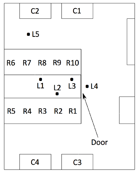
- R1 to R10 are the server racks
- C1 to C4 are the air conditioning units (velocity inlet at the front of the machine and pressure outlet at the top)
Thank you in advance for any insight you might provide.
Pol