Continuity problem with a multiphase simulation

Hey,
i have again a time continuity problem with my multiphase (Water, Air) simualtion. It should be a rain overflow in the sewerage simulatet.
Here is the Link to the projekt.

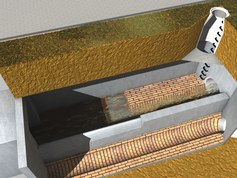
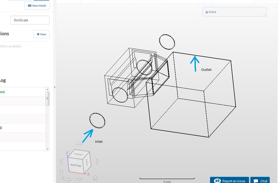
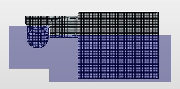
The picture shows you the geometrie. The BC1(Inlet) is a Velocity inlet with 2 m/s, the BC2(Outlet) ist a pressure out, but the Water should not reach it.

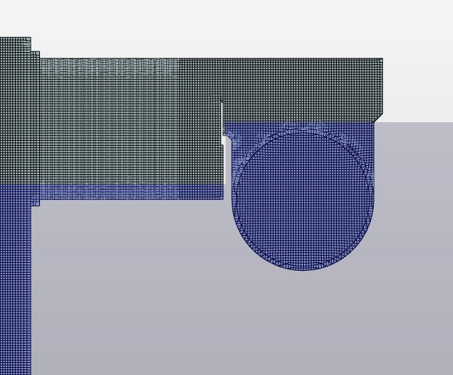
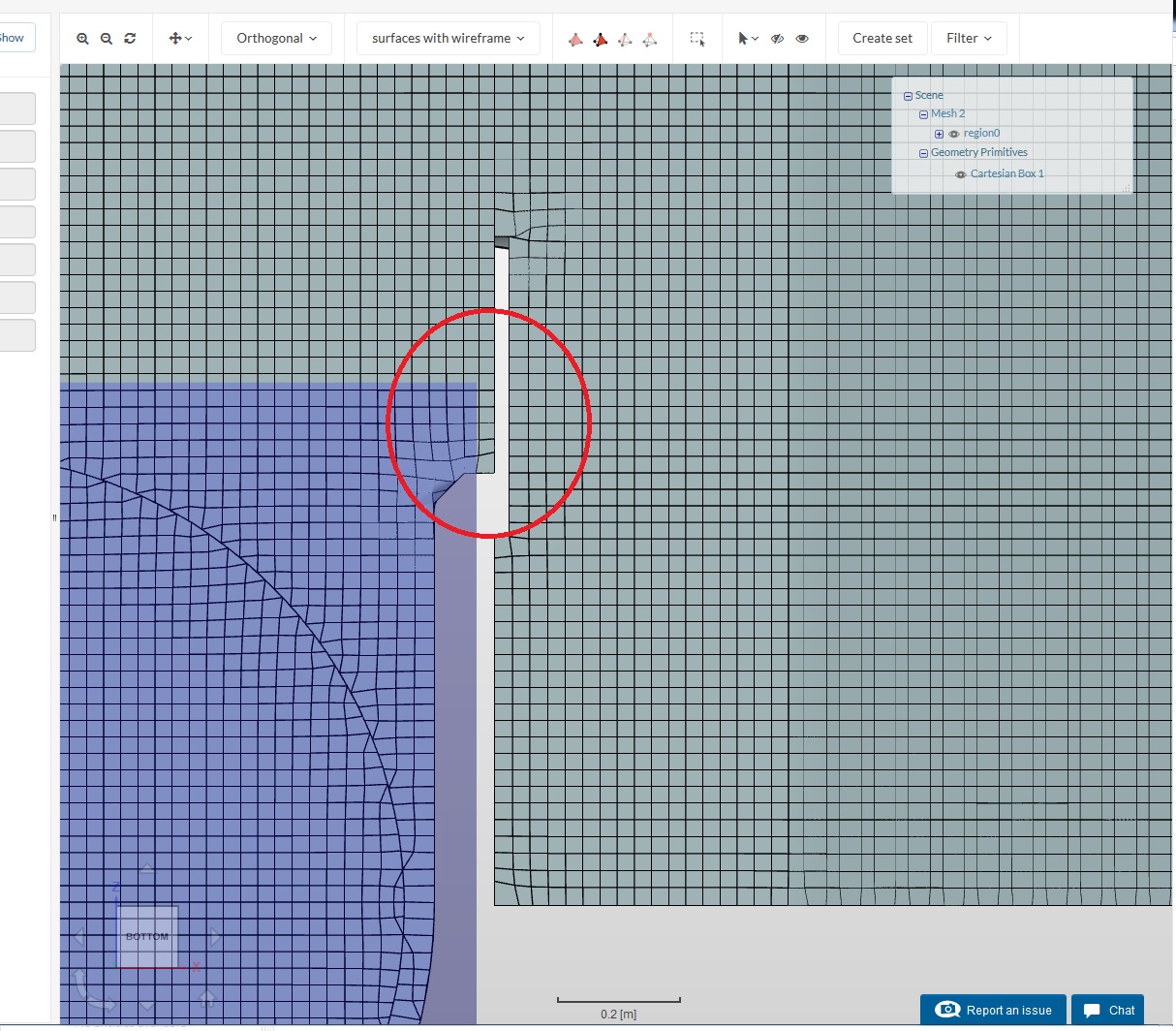
At the first try i used the set numbers for the mesh in x,y, and z direction, furthemore i had problem to see and select the inner walls for the mesh refinements. The walls of the rectangular basin are very thin.

Mesh 1 Run 2:
I used a cartesian Box at the inlet, filled with Alpha phase 1. In order to run over quick.


But the sim stops at 54%.

Mesh 1 Run 3:
I used a second cartesian box an the bassin, also filled with AP1 (Water).
SS3
It stops at 53%.

Mesh 1 Run 4:
The second CB is 0.2 m higher at Run 3.
SS4
It stops at 69%.

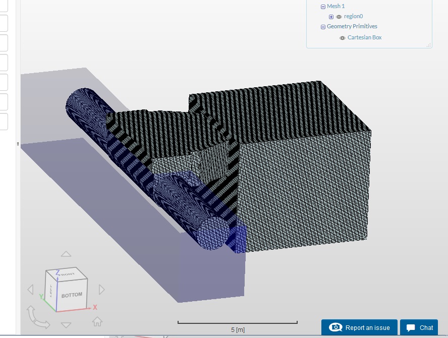
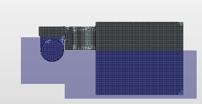
Now i make at second Mesh with thicker walls, so that i can easly see and select it, to make the mesh refinements, i also use approximatley the double count of cells in x,y and z direction.

The boundary conditions are the same like Mesh 1.
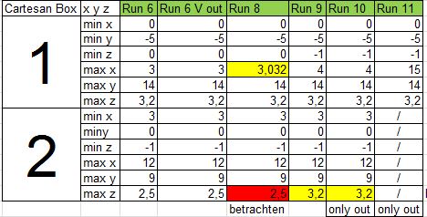
Mesh 2 Run 1: I used only the inlet pipe cartesian box 1.
Mesh 2 Run 2: Add a second cartesian box at the basin with the high of 2.5.
Mesh 2 Run 3: Change the high of CB2 to 3.0.
Mesh 2 Run 4: Change the high of CB2 to, 3.4.
Als Runs are broke up at app. 40%-60%.

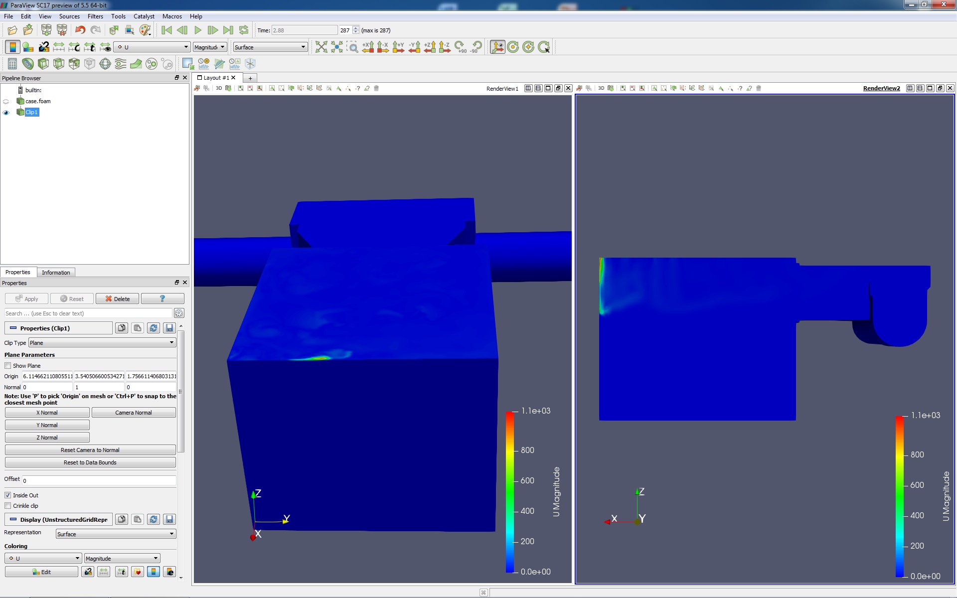
Here is a screenshot from the last second of Mesh 2 Run 1.
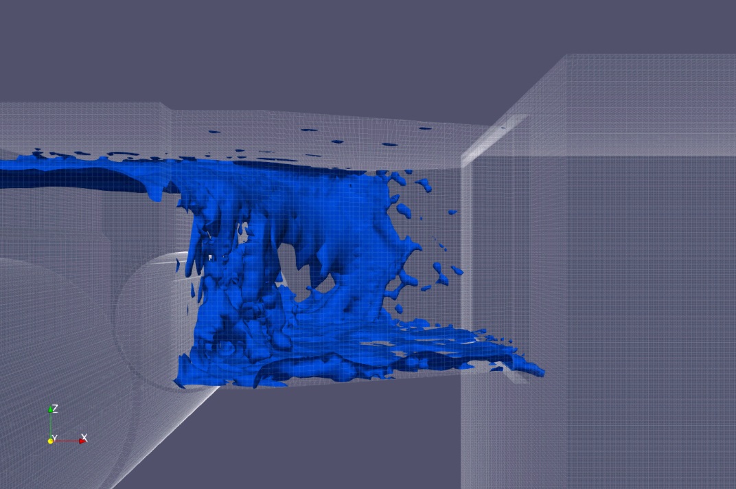
Maybe it helps.
Why is the calculation stops at around 60% every time ?

Thank you for your help.

Kai

Hi @Kai_himself!

Again an awesome case you are trying to solve here! :slight_smile: What I am wondering about is the boundary conditions. You defined only one inlet and a single face as an outlet. Where is are your walls defined and what happens to the other inlet (I suppose it should also be an inlet) ?

All the best!

Jousef

1 Like

Hey @jousefm,
Thank you for your answer.

oh, it is so bad ? :slight_smile:

No, the rain overflow is used to seperate the rainwater in the sewerage. The sewage plant is not able to handle so much water. So you have do seperate the dilute rainwater into a river.

The first idea was to let the pipe waterlevel rise, to get over the sill into the basin. Im still trying with the right boundary condition for the pipe outlet, with a “normal” pressure outlet, the waterlevel are dont move up or down. So i decide for this try, the pipe output is negligible. The other effect is, i became a nice wave over the sill :).

When i will start the simulation i got a report “for all missing boundary condiotions are assumed to be a no-slip wall boundary condition”.
Is a manual definded of walls “better” for the stability of the simulation ? Then i will do and try it again.

Here is a picture of a example Rainoverflow from Wikipedia.

Greetz Kai

Hey @jousefm,
mybe i found something, i think, i have read somewhere, that you look for big velocity gradient on walls. The inlet velocity is 2m/s, i got a area with a velocity of roundabout 1000m/s.
Is this why my simulation breaks up ?

Greetz Kai

Hi @Kai_himself!

That makes no sense and there is something weird going on - having a look at it in the evening if that’s okay. :slight_smile:

All the best!

Jousef

1 Like

Hey @jousefm,
i check the other runs, the have all at the last sim step a little spot with a very high velocity.
Did you find anything out ?

Greetz Kai

Hi @Kai_himself!

Could not find out so far what the issue might be. I had an idea what it could be but that did not work out unfortunately. Will test another run later on and let you know. @Get_Barried, did you find out anything new?

Best,

Jousef

1 Like

Hi @Kai_himself,

Sorry Kai, I saw this post when you posted it awhile back but was caught up by my work.

So I’ve a quick preliminary look and yes your guess of the sudden acceleration of flow to unrealistic speeds is causing your simulation to crash. This brings me to suspect this is because you’ve assigned the “square outflow” to be a pressure outlet which would be fine but you still have air within the geometry for a inlet that is completely filled with water. This causes the air to create a kind of “vacuum” when eventually all the air flows out of the geometry and the solver just completely crashes as it runs into some sort of continuity error.

Based on what your test case is, I would suggest somehow matching the actual “overflow” case by having a phase fraction inlet that accounts for the amount of air entering the geometry as well as an actual outlet for the end of the pipe rather than forcing all the flow to exit through the “overflow” area. Let the simulation run and hopefully we’re able to achieve a high enough mass flow rate that causes the overflow by fixing the outlet flow rate such that the inlet flow rate is larger than that of the original pipe outflow rate.

As for the specifics of how to do this, I’m not too sure myself. I suggest we work step by step to solve it issue by issue while keeping in mind that we need to “replicate” the actual overflow scenario.

Cheers!

Regards,
Barry

2 Likes

Hey @jousefm and @Get_Barried,
ok, i will try it. Thank you for your answers !

Greetz Kai

1 Like

Hey @Get_Barried,
so i make a first try, with the opposit pipe outlet.
It has the half velocity like the inlet, but the sim broke up at ca. 50%, again with a high velocity spot at the top.
Run 7
Greetz Kai

Hi @Kai_himself,

The Cartesian box still doesn’t cover the area where flow is supposed to overflow and the solver is unable to allow flow to overflow in the specified area. Try extending the box to cover the ledge and gap between the two boxes and see if it works, do refer to the picture below.

Cheers!

Regards,
Barry

1 Like

Hey @Get_Barried,
so i ran a few simulations with different cartesian boxes.
Have i understood that correctly, do you mean this gap between the two boxes ?


This are the runs and the expension of the boxes.
Pic2a
Now i try a inflow with a Phase fraction value of 0.99.

I will get back.

Kai

Hi @Kai_himself,

Yup that is the gap I am referring to.

Do let me know how it goes.

Cheers.

Regards,
Barry

1 Like

Hi @Kai_himself,

Any progress so far?

Cheers.

Regards,
Barry

1 Like

Hey @Get_Barried,
Thanks for the question. No, not as desire :(, i got 20 Runs with different conditions, but every run got an continuity issue, and at the last simulatet frames i got a little spot with high magnitudes.

To fill the Gap between the two cartesian boxes i deside to use only one Box, is it ok or did you have other experiences ?

I make a Excel chart with some specification about every run. I cant upload it here, so i got it to google.

Greetz Kai

Hi @Kai_himself,

Well that is unfortunate. I’ve requested permission for access to the file, can you grant it?

Cheers.

Regards,
Barry

1 Like

Hi @Kai_himself,

May I suggest making a much simpler overflow case to see if that can work? Once we have the settings for that correct we can translate them over and deduce where the issues lies.

Do let me know.

Cheers.

Regards,
Barry

1 Like

Hey @Get_Barried,
yes of course, its ok.

Greets Kai

Hey @Get_Barried,
i build a simpler overflow, do you think its simple enough ? I creat e it on onshape here is the link.

Greetz Kai

Hi @Kai_himself,

It looks good. When you import it do ensure it says it is watertight and go ahead to see if it runs. Be mindful about the need for air to escape the geometry as well besides water.

Cheers.

Regards,
Barry

1 Like