I’m having trouble constraining and relating the two yokes and cross in a universal joint assembly. I would like to see the stresses when the yokes are under an axial, tensile load. It seems like pinned connections should be the way to go, but I get “solution matrix is not factorizable” errors. Any ideas?
Thanks for posting your question. This issue is generally related to the over constrained conacts and boundary conditions, but I see that you have figured it out. Please let us know if you need any other help.
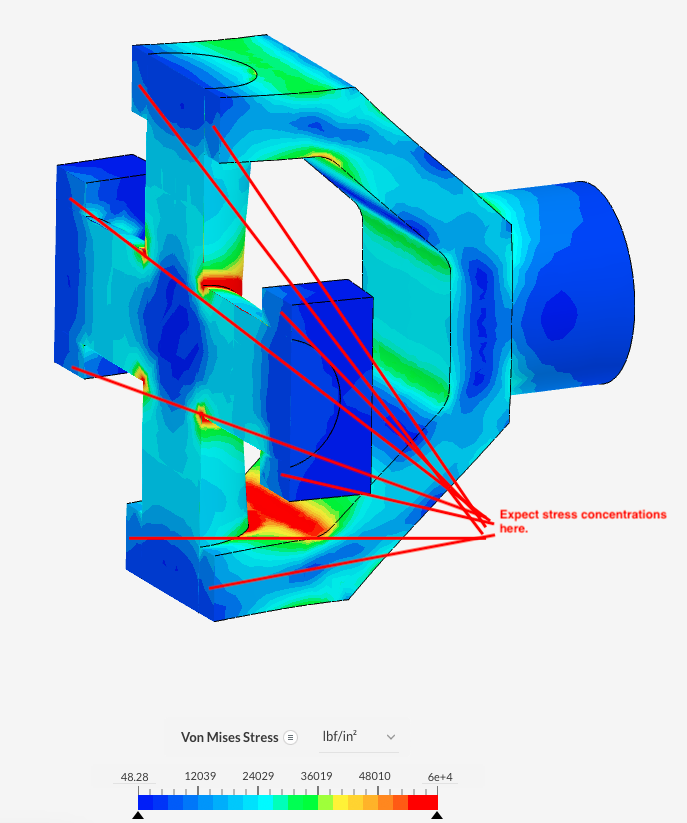
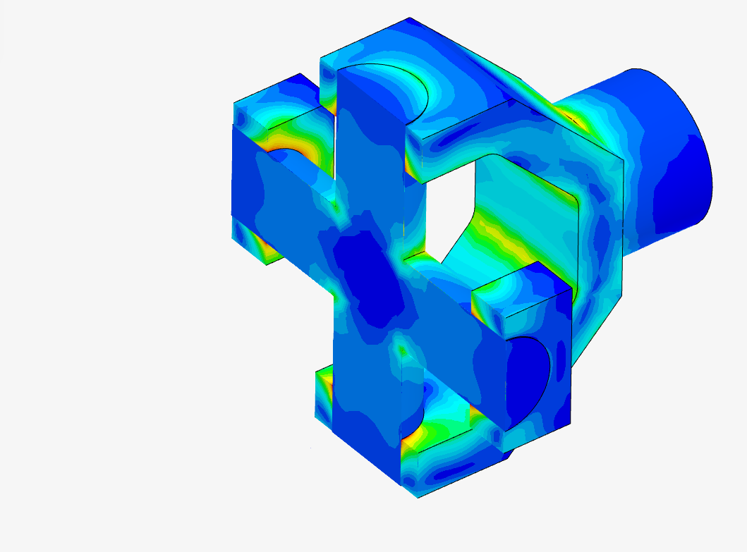
I can get it so sim with bonded contacts, but I’m not sure they’re a good representation of reality. In this sim, the right yoke is being pulled to the right by 10,000 lbf. I would expect the load to be transferred through the sides of the yoke surrounding the cross. However, as the picture below shows, most of the load is pulling on the right face of the cross, as if the metals were welded together.
No sliding contact setup has worked for me. I’ve tried several mesh settings and a refinement.
One point I would like to highlight is that the stress moving to the center of the intermediary part (coupling) seems intuitive and consistent with the current simulation setup.
@ldon1234 ,
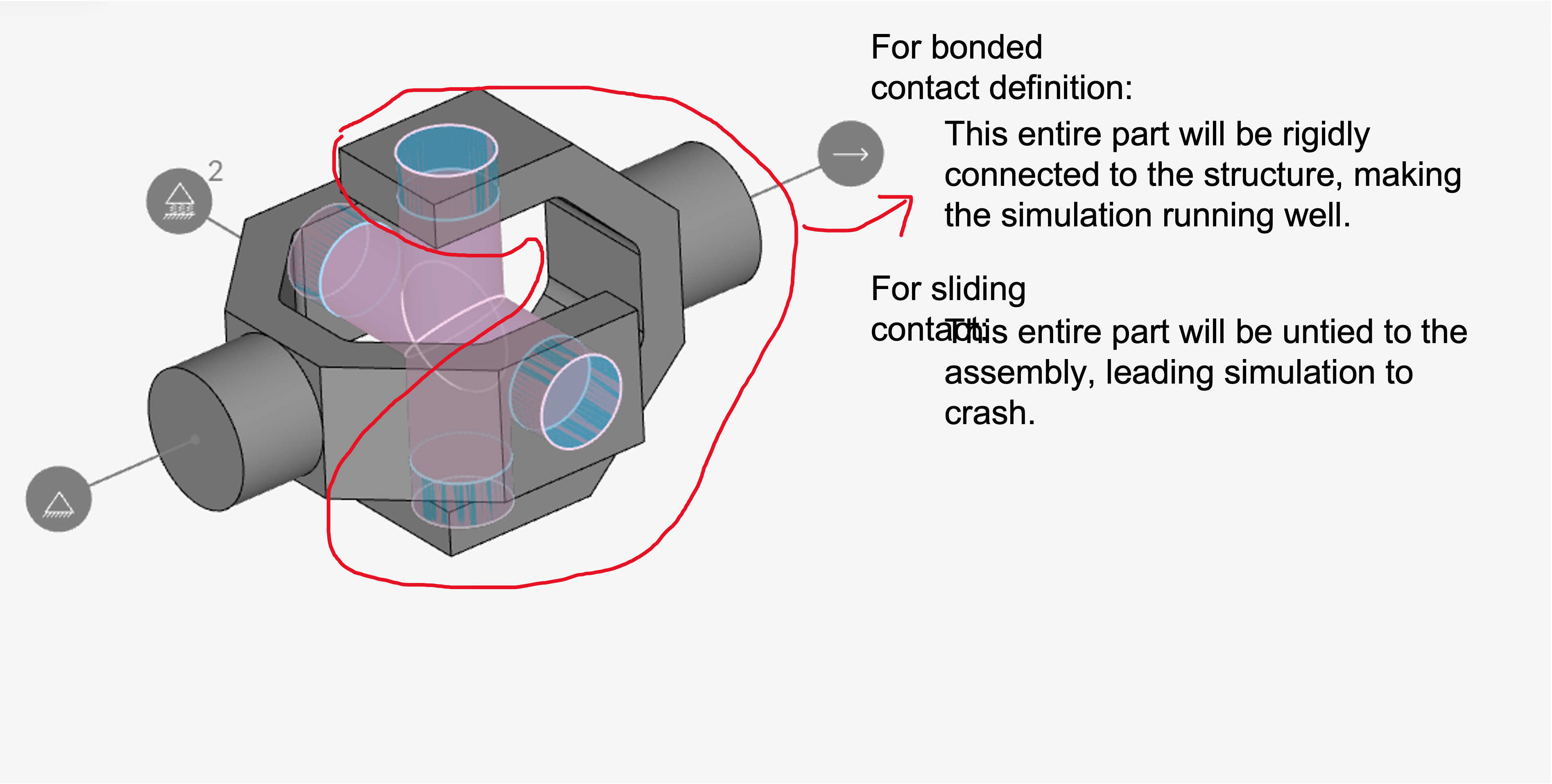
as @goncalves mentioned, the seem stress behavior is consistent with using a bonded (glued) contacts.
Also with sliding contacts you will not get a “real” stress distribution, as there es well faces in contact will transfer tension forces - which is obviously not the case in reality.
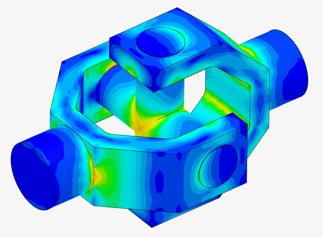
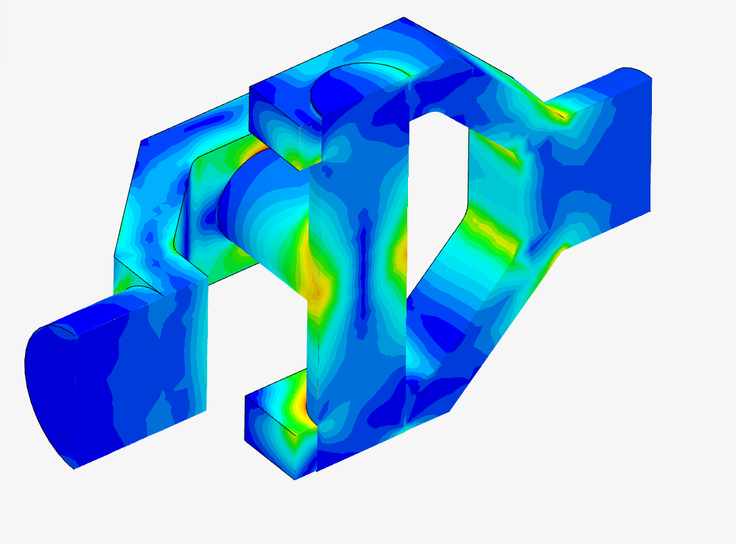
If you however replace the bonded/sliding contacts with “physical contacts”, you get the following stress distribution, which seems more reasonable: