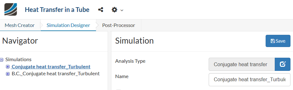
I’m trying to model a square tube with a fluid flowing through it and a heat flux applied to one of the faces. I’ve done this successfully using the standard interface coupling (and I’ve found a number of bugs as well), but now I need to know how to specify boundary conditions (ie roughness) at the material interfaces. Is there a way to do this?
Link to project: https://www.simscale.com/workbench/?pid=5473321753949019793#tab_0-0
Hi @dldrewniak!
You have 5 runs, please, for which simulation are you referring? Having a first look, the geometry has some overlapping interfaces but I need to know more about what simulation and what bugs you are reporting.
About boundary conditions (roughness), you can set this one in Boundary Conditions → Type: Select “Custom” → Turbulent kinect energy: Select “Wall function” → enable roughness.
Please, let me know if it works for you ![]()
Cheers,
Vinícius
How do I set a BC for a surface that also has a coupled thermal interface?
The bugs, or unexplainable results based on the BCs, have to do with using mass flow rate as the Velocity Inlet BC variable instead of one of the other options, the Pressure results not making much sense, and the fluid density that the Post-Processor shows being incorrect.
Whenever I use mass flow rate as my Velocity Inlet I get flow velocities an order of magnitude greater than I would expect them to be. Using the other Velocity Inlet BCs my results are as expected. This can be seen under the simulation “Conjugate heat transfer_Turbulent” for run “m_dot_0.5, q_1e3”. SimScale
Another issue I found was when using the Conjugate Heat Transfer module, the fluid pressure doesn’t seem correct. I am expecting to see a large pressure drop along the pipe, but the value is quite low. When using the same BCs and geometry in the Incompressible module I get results that were expected. (SimScale)
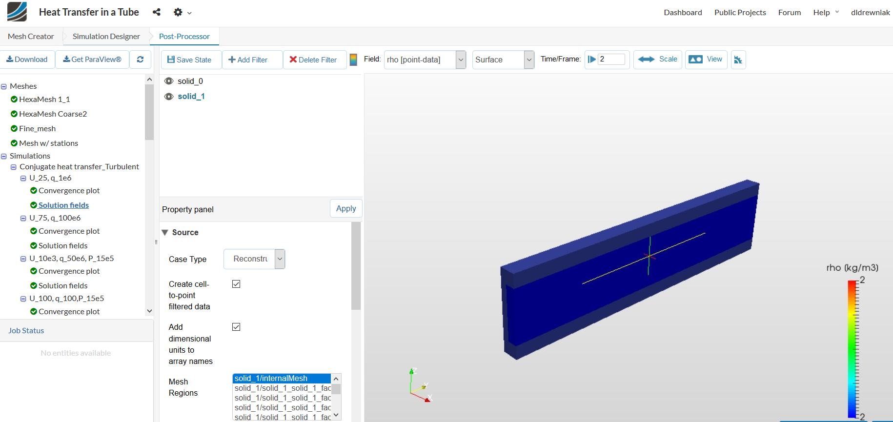
Additionally the values for the density of the fluid (in this case water) are off in the Post-Processor. I set the density to be constant at 997 kg/m3, but the Post-Processor display the density as being 2 kg/m3.
Hi @dldrewniak,
Your question on setting up BCs will have to be answered by the other PowerUsers such as @vgon_alves as I am still relatively new to CHT.
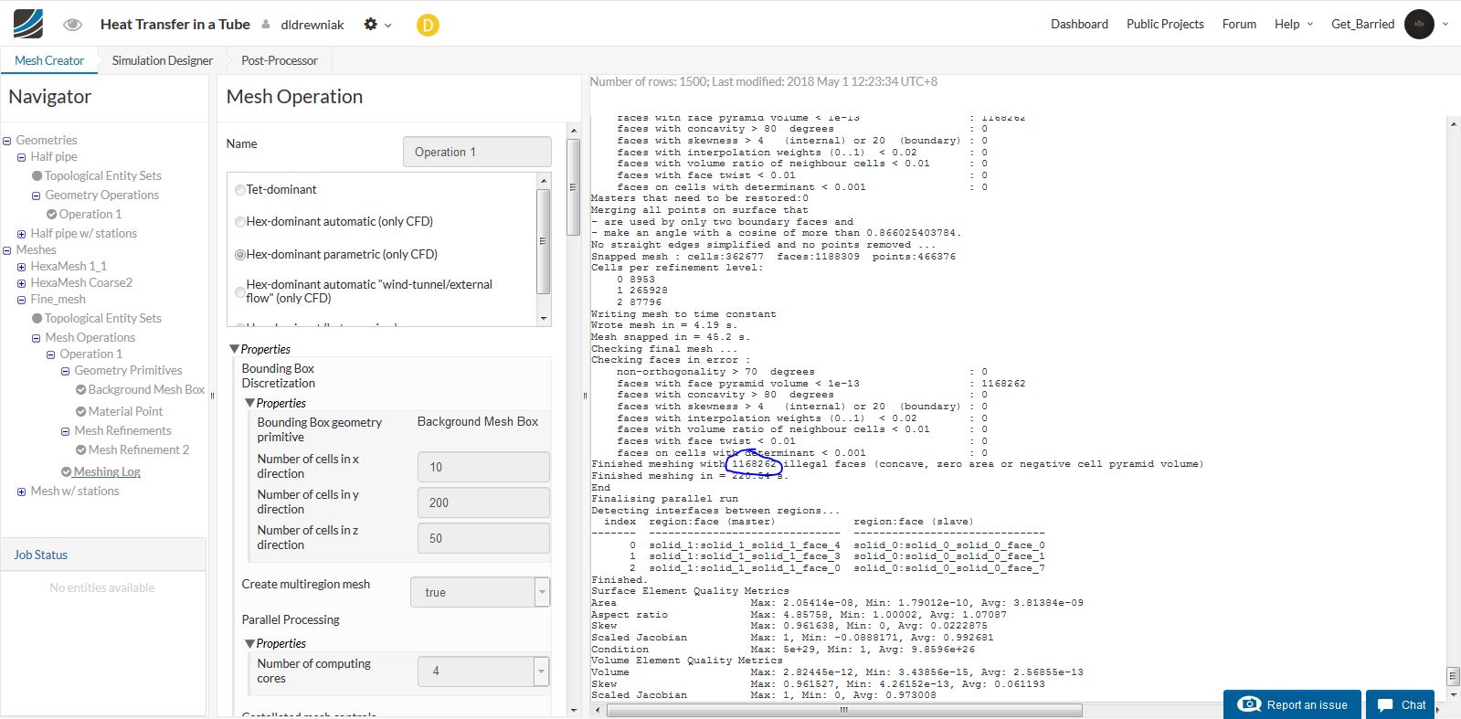
On the other hand, I was checking through your simulations on any potential problems and I noticed that your “Fine_mesh” has over 100,000 illegal cells and cannot be used, so do take note.
For the “Heat Transfer in Tube” project I don’t see a run with the CHT. Has that been deleted? The geometries involved are relatively simple so this issue primarily lies in setting up of the BCs and maybe even an insufficiently fine mesh. I would suggest re-checking all your calculations especially for the mass-flow rate, the initial fluid velocity and the ambient pressure/pressure outlet.
Which run and project was this?
Cheers.
Regards,
Barry
Thank you for the heads up about the mesh. Where in the meshing log does it say how many illegal cells there are?
I posted the link to two different projects in my last reply. The only type of simulations I’ve done in “Heat Transfer in a Tube” has been CHT. The other one I only did Incompressible flow.
I didn’t think to check if the mass flow rate BC works with a finer mesh. I figured since the freestream and mean value options worked then the mass flow rate BC would work as well.
All of the runs under the project “Heat Transfer in a Tube” show the fluid density at 2 kg/m3.
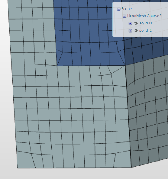
Sidenote: I tried to keep the mesh I’m using for this simulation relatively rough since I am just trying to learn how to set up the analysis and I wanted to do a bunch of quick simple runs, but the cells didn’t come out perfectly. How can I straighten out the mesh divisions in the corners of the surfaces in the future?
Hi @dldrewniak,
You can find them in the meshing log near the end. I have attached a screenshot that you can see below where the illegal cell count is circled.
Isolation of problems to specifics by changing one variable at the time should help in identifying the issue. However, things do seem correct the way you setup. Could be that my lack of experience in CHT playing a part in me not being able to spot issues. Lets see what the others say.
Increase of surface refinement should help. This seems like a snapping issue, and if you wanted to maintain the same level of fineness but fix up the mesh then you will need to delve into the fine tuning options in the Mesh Operations for the mesher which is quite complicated so I wouldn’t recommend doing so without extensive reading on how the mesher (SnappyHexMesh)'s parameters function.
Cheers!
Regards,
Barry
Hi @vgon_alves,
I cleaned up my project a bit and now only have one simulation for you to look at. I still need helping determining how/if a boundary condition can be applied to a surface that is also a coupled thermal interface.
Thanks,
David
Hi @dldrewniak,
Firstly I’d like to say sorry for the delay!
So, please have a look at these points:
- The response to your question is “no, you cannot set two BC’s for the same face”. Being that the interface called “Inner wall” is your first BC and the Roughness is your second one for the same face.
- Make sure that you are setting the gravity as a propertie in one of the axes (Simulation designer → Model → Gravity).
Once again, sorry for the delay and let me know if the things are clear now.
Cheers,
Vinícius
Will do. So how do you recommend I go about comparing the heat transfer capabilities between a smooth and rough pipe? Should I just model the fluid flow in the Incompressible Flow module and split the geometry up into different stations to simulate the wall and set each station with it’s own temperature and heat flux BC?
I do not know if this is the best approach for you, because it may be manually complex for you to define the best dividing regions to set the variables and it may compromise your results. So, I suggest you to continue with the CHT simulation excluding the “Inner wall” setting the Rounghness in your BC as you did before, but don’t forget to set the gravity and set the 2 walls with Roughness (solid and fluid faces). In the case that you do not set the 2 faces a no-slip wall boundary will be assumed for unassigned faces, and a thermal coupling for unassigned interfaces with an automatically way and your simulation problably will crash.
Please, let me know if it works for you.
Cheers,
Vinícius