I created a new simulation project called 'Compressor':
This project simulates air flow through a Centrifugal Compressor.
More of my public projects can be found here.
I created a new simulation project called 'Compressor':
This project simulates air flow through a Centrifugal Compressor.
More of my public projects can be found here.
This project simulates a airflow through an automotive turbo-charger’s ‘Centrifugal Compresor’ using the Steady State, Multi-Reference-Frame method (MRF) and K-Epsilon turbulence model.
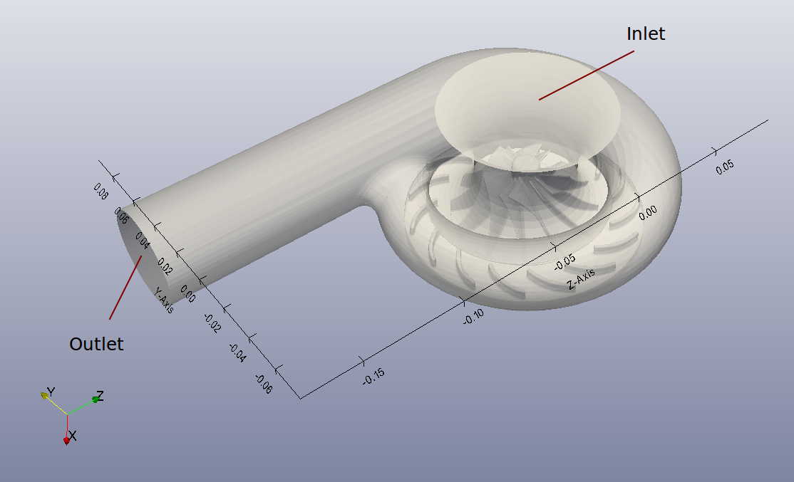
The geometry of the compressor includes an impeller (rotor), diffuser section and volute casing. The initial source of the geometry was a CAD model by GrabCAD user Andreas Gkertsos . The figure below gives an overview of the overall dimensions of the geometry with the flow inlet and outlet as shown. For the rotating Impeller a separate region was created to specify the MRF zone.
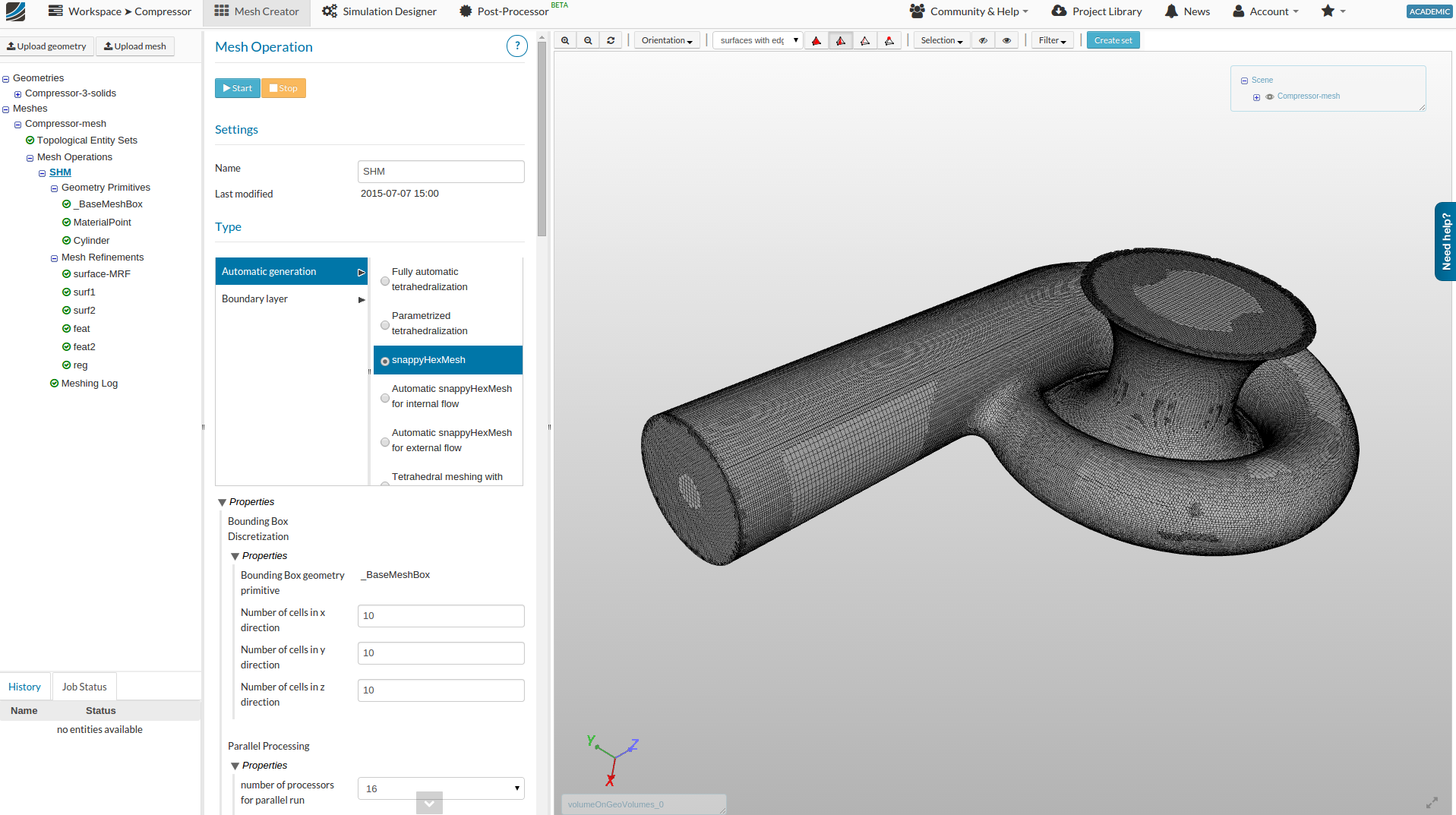
The geometry domain was meshed using the ‘Snappy-Hex-Mesh’ on the SimScale platform and the mesh consists of about 2.6 million cells and is depicted by the figure below.
The boundary conditions chosen for this sample project were a mass flow condition for the inlet face and a static pressure condition at the outlet face. The flow parameters selected for the compressor are arbitrary and were estimated based on general performance curves to show a sample operation. The fluid was ‘Air’ at standard conditions. For the inlet face a mass flow of 0.1 kg/s was used while a static pressure value of 103600 pa at the outlet was taken. The rotating zone was assigned an operational velocity of 3000 rad/s (approx 29,000 rpm).
The simulation took around 11 hours on 8 compute cores and analysis the mean velocity and pressure field in the Compressor. The results below (processed on ParaView) show the pressure rise, velocity streamlines and density changes at cut sections of the Compressor. The simulation provides insight into the flow field inside the compressor for a given mass-flow and rotational speeds.
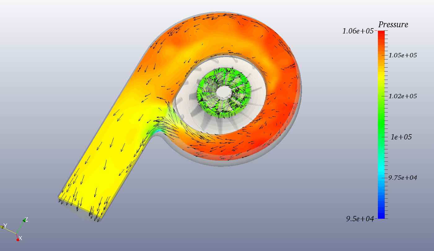
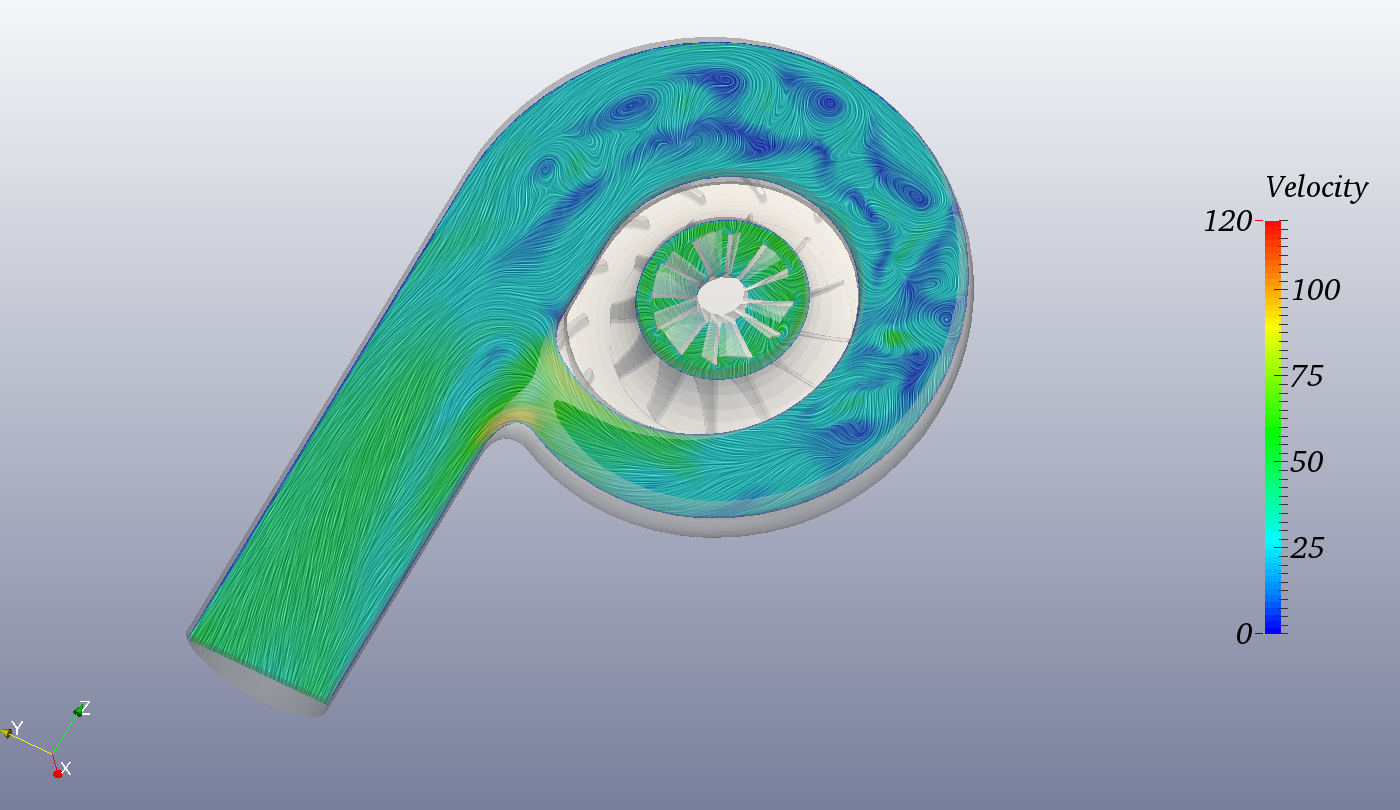
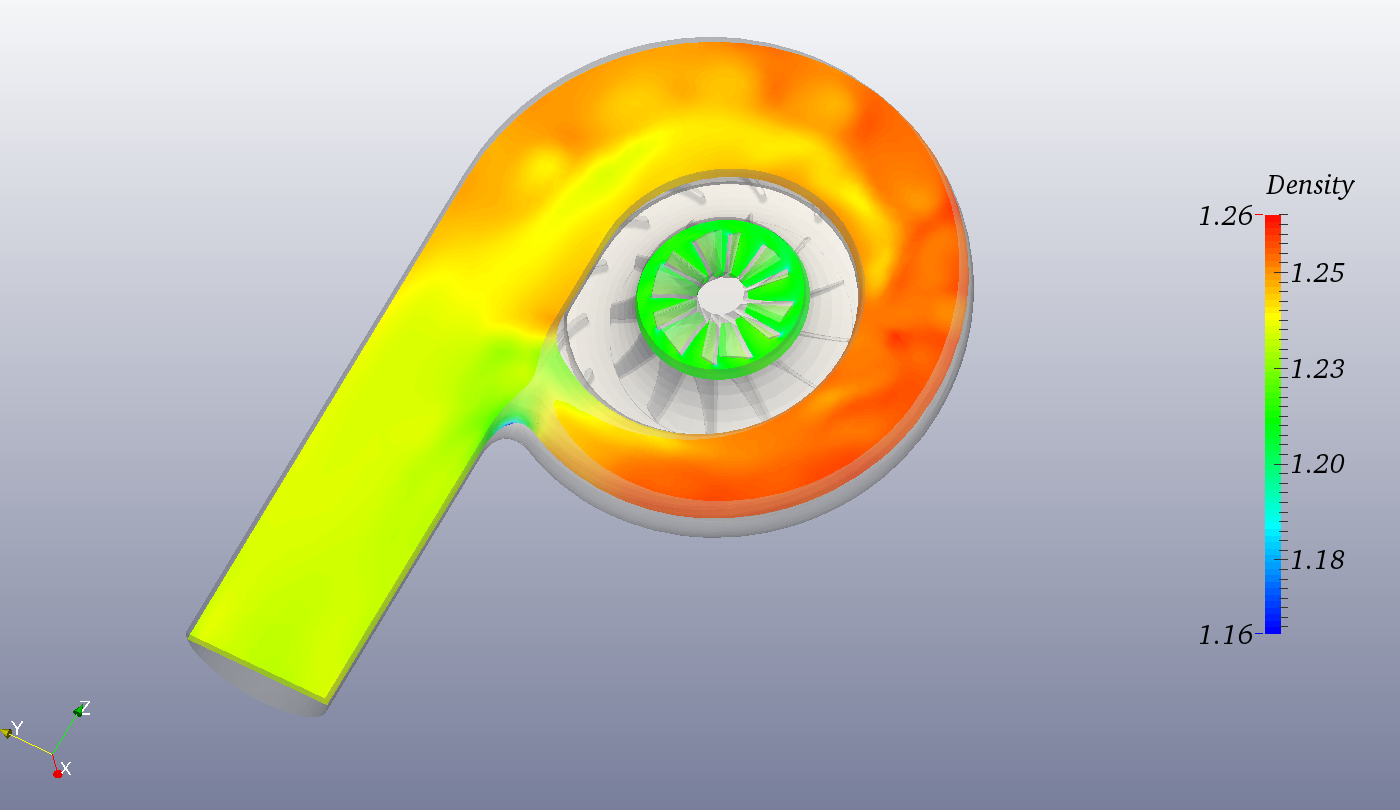
The flow variable for a slice through X-axis at mid height are shown by the figures below
Pressure:
Velocity:
Density:
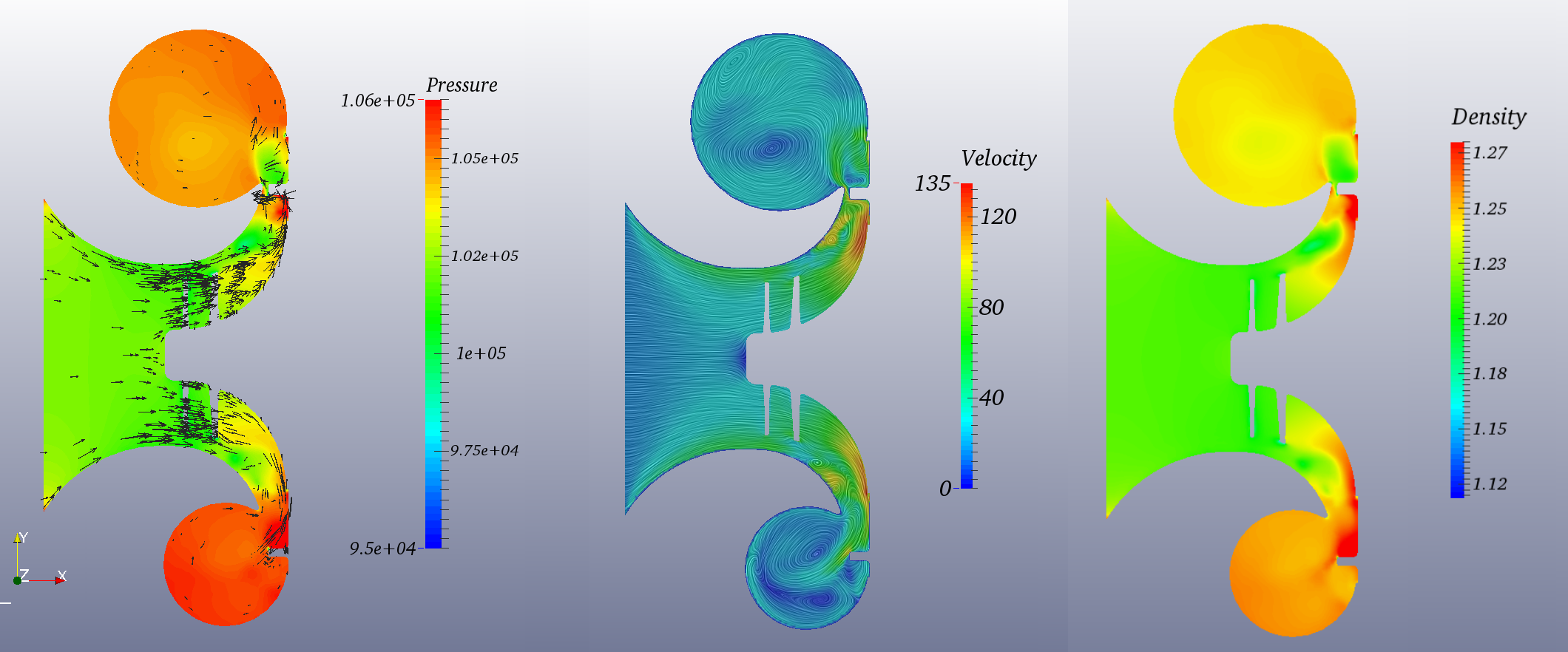
The flow variables for a slice through Z-axis at the inlet center point are shown by the figure below
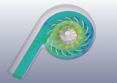
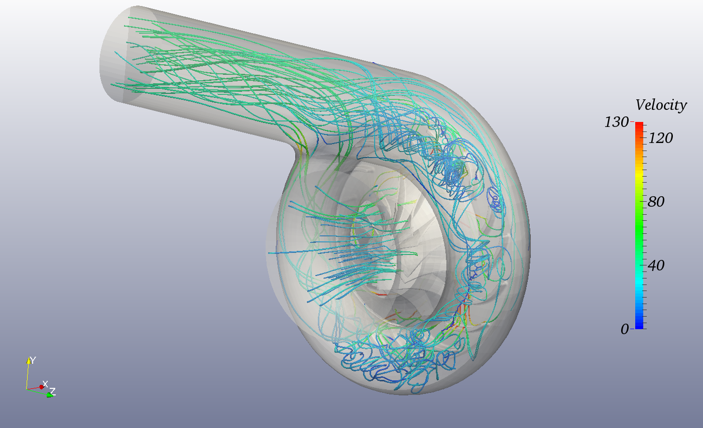
The figure below depicts stream-lines colored by velocity.
Your rotor is orientated and spinning in the wrong direction vs the diffuser and volute.
As such the results are useless.
i noticed immediately as well. Wow and the volute looks suspect expansion area.