Hey !!
Please go through the following project, and let me what exactly did I miss.
AIM:
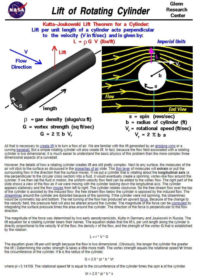
Trying to validate the case of Kutta-Joukowski theorem for the flow around a 2D rotating cylinder.
For my project, following are the specifications,
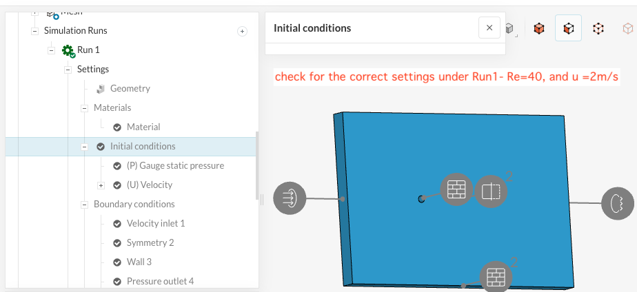
Radius =0.2m, density =1 kg/m^3, kinematic viscocity = 0.02,
Consider the first case for Re=40, i.e, incoming velocity =2 m/s. Here I calculated spin velocity as spin vel = incoming vel/ radius =10.
As per the theorem,
- circulation = 2piRadius^2 * spin velocity(rad/sec)
*Coeff of lift = circulation / (radius x flow velocity)
*Lift per span= density(=1 kg/m^3)x flow velocity x circulation
However, the coefficient of lift value which I am getting is different from what is expected.
I have used laminar steady model. However, I also tried with k-omega sst, and laminar unsteady too. However, all are giving almost the same results. I am doing some mistake in the simulation set up.
I rechecked the directions(axis), and boundary conditions for each, and found all correct. I have no idea where am i going wrong. Can someone check the setup in the following section(as I have tried different set ups, which basically gives almost the same results. ):
Also, I tried lowering the spin velocity, as the spin and incoming velocity are independent of eachother, however, even there, the same thing is happening.