I am in my final year of engineering (Aeronautical) and I am interested in fluid dynamics. Recently, I read few papers on ‘Co-Flow Airfoil’ and I really liked the idea behind that work. I am willing to do my final year project on building an Electric Aircraft Model which is having Co-Flow airfoil. But, I am not getting enough help from the faculty.
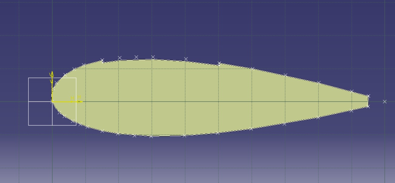
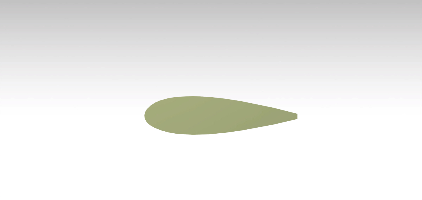
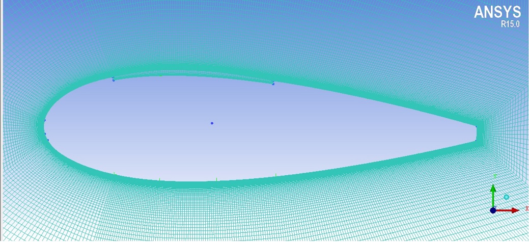
I was interested in running an analysis on the NACA 23024 airfoil. I have built the geometry in CATIA V-5, with injection slot and suction slot (I have kept the slot size same). I generated the mesh in ICEM CFD. Now, I am feeling difficulties in running the analysis in ANSYS FLUENT.
I have employed Spalart-Allmaras 1 equation turbulence model. I am confused about the boundary conditions which I need to employ for the airfoil. I have tried about 100 cases involving different boundary-conditions on injection and suction slot, but, it didn’t give proper results. I read a paper that quoted ’ The simulations were done with free stream conditions of M∞ = 0.3, p∞ = 101.325 kPa and T∞ = 300K. The mass flow rate at suction is 0.2 Kg/s. The injection slot was given as pressure outlet and the suction slot as mass flow inlet conditions.'. I don’t quite well understand that. When I employ the same, again, I am not getting results properly. Can you please shed some light on boundary conditions that I have to employ to get the satisfactory results, please?
Thanks for replying, @jousefm.
I have looked into the works and simulations of flow over an airfoil. But, I am referring to ‘Co-Flow Jet Airfoil’. I cannot figure out the boundary conditions of the latter airfoil.
The external domain would be the same setup as given in the template I suppose and the suction as well as the injection slot can be assigned to a separate boundary condition. I would try it as soon as I am at home and see if my colleagues find something out in the meantime
Yes. The suction and injection slot demand a separate boundary condition. I really appreciate your help. Thank you so much, @jousefm. Hope I get the required help.
@jousefm, when I am having issues in uploading the geometry file. The pop-up says ‘Sorry, the file you are trying to upload is not authorized (authorized extensions: jpg, jpeg, png, gif, mp4).’
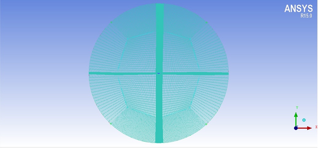
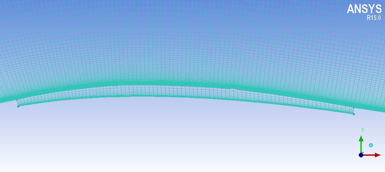
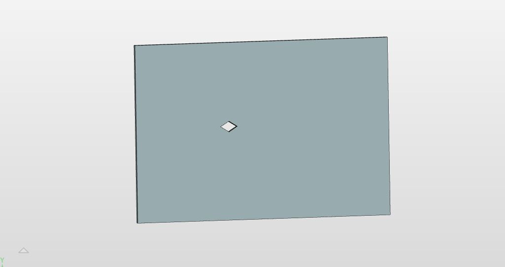
A good workaround would be to create the entire box including the domain while just having the actual aerofoil as a hole as you would also do in ansys. Do refer to the picture below of what I have done for a different aerofoil but concept is the same. This would likely negate all of the issues you are facing.
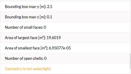
If it s a 2D simulation i suggest the “width” of the plate to be around 0.01m judging by the chord length of your aerofoil and have around a forward area of 5 times the chord length, back area of 10 times and height of 5 times above and below. Make sure to export the file as IGES or STEP or a solidworks part file and ensure it is watertight.
I am sorry for troubling so much. But, I don’t quite understand the warning ‘Geometry is not watertight’. Can you throw some light on that issue? And how do I fix it?
This means that your geometry is one of two things or both, either it is a empty shell that is not a real solid that is just a bunch of data or you have holes within the geometry.
You need to ensure when you construct the geometry in your CAD software you have to apply good practices and not haphazardly just draw out the CAD to get the shape you want.