Hi SimScale community,
I’m a student working on a project called Project ARCTIS — a simplified magnetocaloric refrigeration system using a Halbach array and a Gadolinium (Gd) magnetocaloric bed. I’m trying to run a Conjugate Heat Transfer IBM simulation to generate a temperature distribution heat map across the assembly for a student research submission.
System description:
-
Closed loop fluid system — water circulates continuously through a serpentine channel inside the Gd bed, through connecting stub pipes, through heat exchanger channels, and back through a curved return pipe
-
No true inlet or outlet — the loop is continuous
-
Solid bodies: Gadolinium bed, Copper HX plates, Aluminium housing, Steel pipes
-
Fluid: Water
What I’m trying to achieve: Show heat transfer from the Gd bed surface (fixed at 295.93 K) into the circulating water and through the surrounding solid assembly — producing a colour heat map showing temperature distribution across all components.
What I have successfully done:
-
Uploaded STEP file from Fusion 360
-
Selected CHT IBM as simulation type
-
Successfully extracted Internal Flow Volume — SimScale correctly detected the entire connected fluid path as one body
-
Assigned materials to all solid bodies
-
Set Fixed Temperature boundary condition on Gd bed surface (295.93 K)
-
Set gravity, initial conditions, numerics and simulation control
-
Generated mesh and obtained a result using stagnant water
The core problem: Because my system is a closed loop, I cannot use velocity inlet and pressure outlet boundary conditions — SimScale flags the faces as internal and ignores them. I want to simulate forced flow at approximately 0.2 m/s to show realistic heat transport from the Gd bed into the water and through the pipes, rather than just conductive diffusion from stagnant water.
What I have tried:
-
Pipe split to create open ends for inlet/outlet — SimScale still flags faces as internal
-
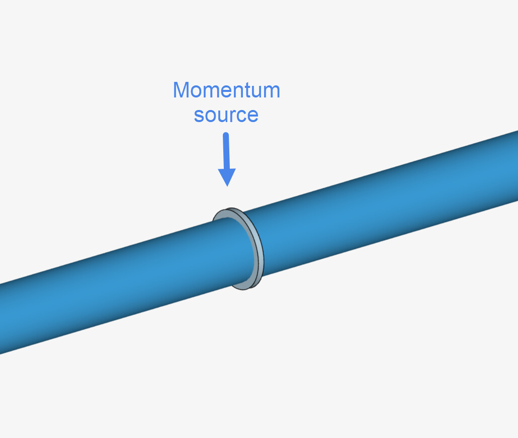
Average Velocity momentum source across entire flow volume — uncertain about direction for complex serpentine geometry with multiple flow directions
-
Fan momentum source — same problem with direction for complex geometry
My specific questions:
-
What is the correct SimScale approach for forced flow in a closed loop CHT simulation?
-
Is momentum source the right tool, and if so how should direction be configured for a multi-directional serpentine geometry?
-
Is there a better simulation type for this specific case that still captures fluid-solid heat transfer across the full assembly?
Thank you in advance.