I had a quick look at could not notice anything. Perhaps try setting a smaller delta T in the simulation controls, otherwise start again and follow the tutorial more carefully as you have most probably missed something. Your initial force values are very unstable.
To begin with, it is normal that the results of the two cases are different, because the tutorial is based on F1 conditions, and as you can see the inlet velocity is 80 m/s, whereas yours is 20 m/s. So the numbers shouldn’t make you worry, they are pretty typical for an FSAE rear wing at this velocity.
Now about the instability, I think you should follow @roy_g 's advice as a first step. Make sure to come back if it is not resolved.
After going through your case setup, I’d suggest setting the initial velocity field (0, 0, 0). I’ve read some materials that suggest that using initial fields for U is not recommended for most steady state cases. This would also be something to check, as it might be causing these huge variations early on in the simulation.
Furthermore, consider using second order accurate discretization schemes to achieve more precise results.
/Ric
Edit: I made the following changes to your set up:
changed the initial velocity field from (20, 0, 0) to (0, 0, 0);
activated potential foam initialization in simulation control.
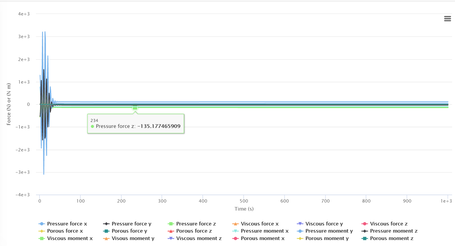
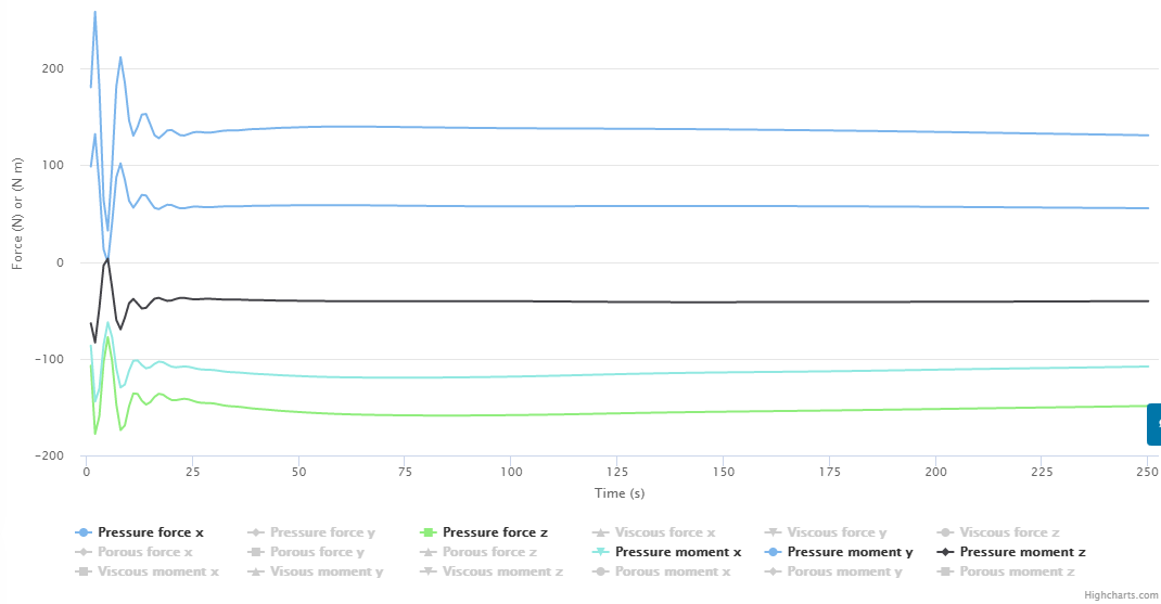
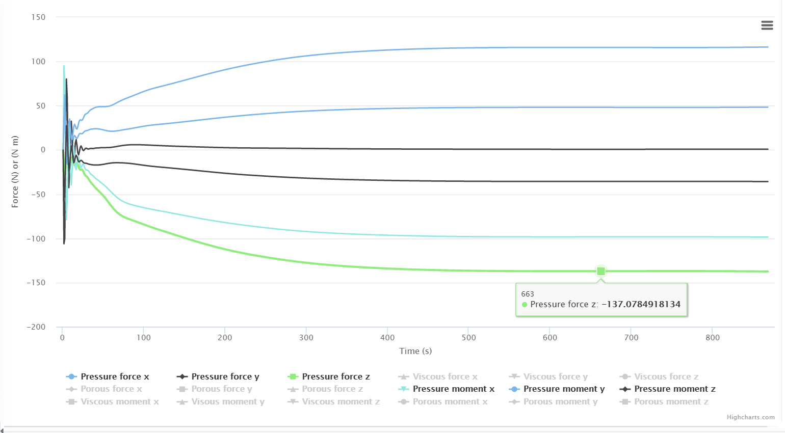
Then I ran the simulation for 250 iterations just to see the behavior of the force plot (it hasn’t converged yet):
I agree with Ric. I noticed that you used first-order schemes. This type of schemes usually results in good stability for the simulation. As a consequence, convergence commonly occurs faster. Thus, converging quickly doesn’t necessarily imply that there is an error in the simulation.
However, you have to keep in mind that first-order schemes produce results that are not as accurate as second-order schemes do. I suggest that you try out a simulation using second-order schemes to get final results.
If you would like to understand more about schemes:
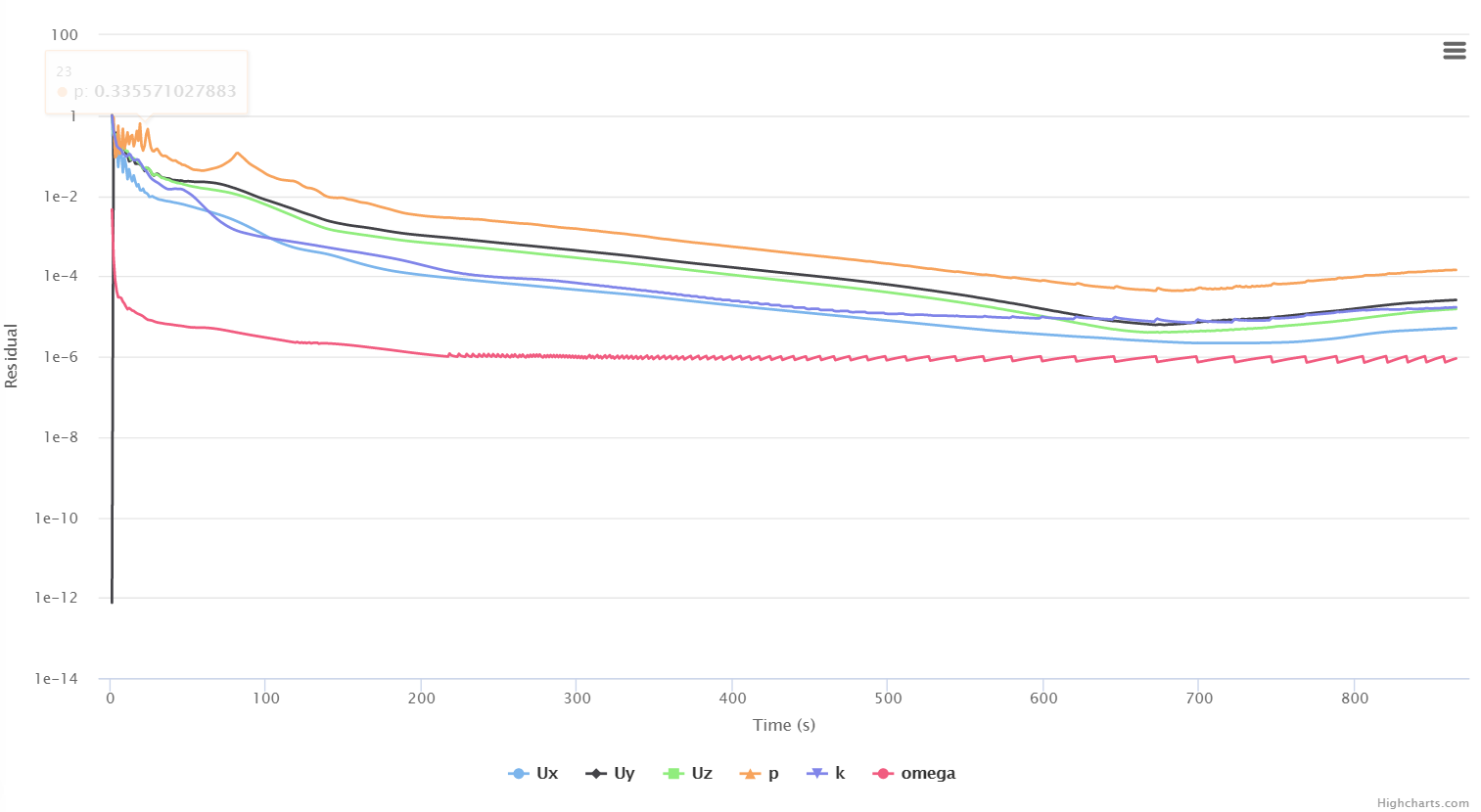
It looks to me like the residuals are just going through a bump before they descend again… and that the individual forces are not stable yet (you can not tell with more than one force shown on the force plot, nor with the number of iterations greater than the last number of iterations you want the forces to be stable over)
If you truly want to POSSIBLY have accurate results, each individual of the 6 xyz FORCES should be stable for MANY of the last iterations (I look for <1% stable over last 500 iterations, and preferably <0.2% when you are sure that you have ALL simulation parameters/numerics correct and that you have a very good mesh).
Again, that is, each force must be stable (no need to look at moments stability, stable forces will ensure stable enough moments).
So, do not look at force plots with more than ONE force variable showing at a time and only over the last number of iterations of interest (500 in my case), that is the only way you can tell if that particular force is stable.
Forces that are close to 0 will take the longest and are the hardest to make stable by the rule. They will need special consideration.
Hi again! I might have very basic question but Im just starting with cfd. If I apply symmetry condition, these forces on the plot come from the whole part or should I multiply it by 2?
If you’re using half of the model + symmetry BC, then forces in the lift & drag directions have to be multiplied by 2 in order to get results for the whole structure.