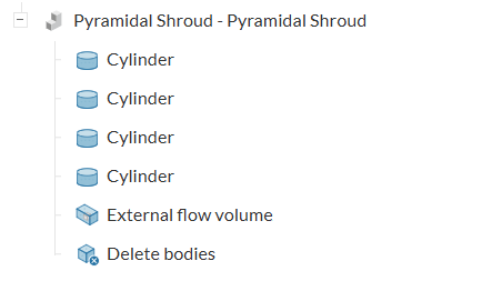
Hello All!
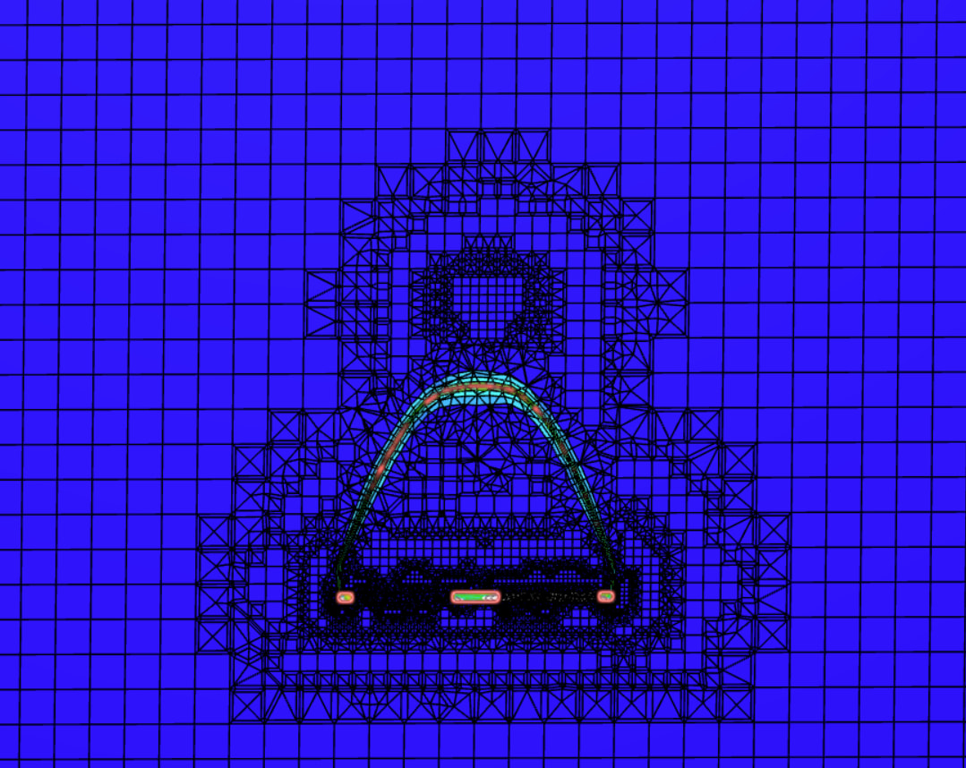
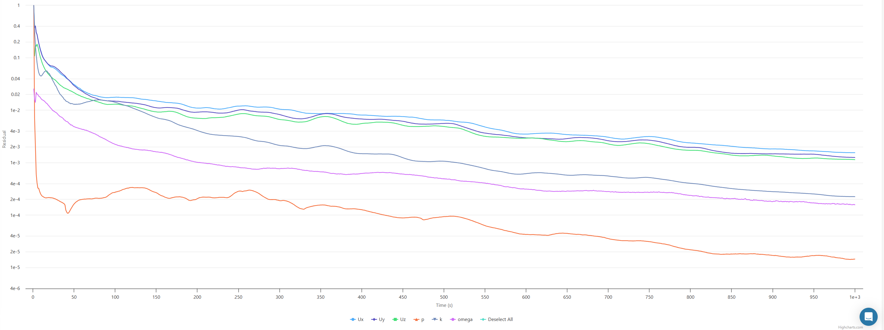
I am working on a custom drone shroud and was hoping to get some help with the simulation as it is not looking correct to me and I have tried a lot.
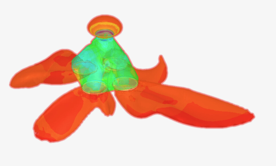
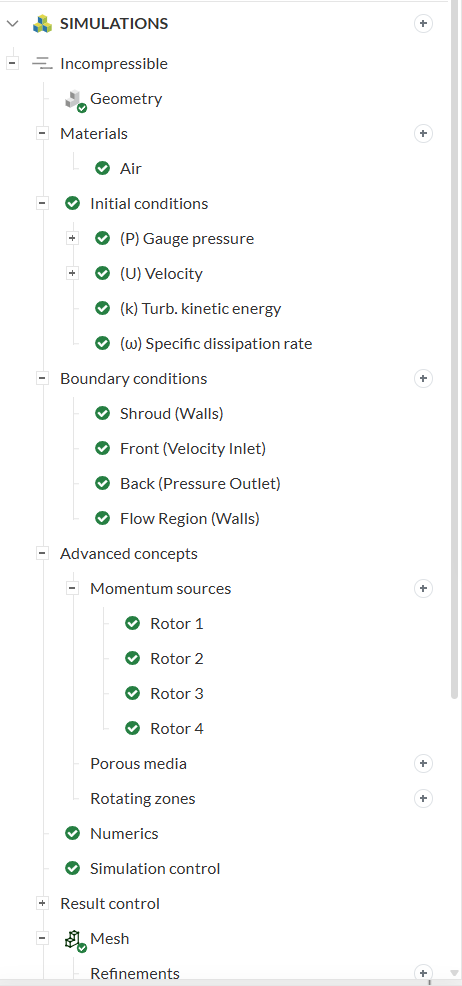
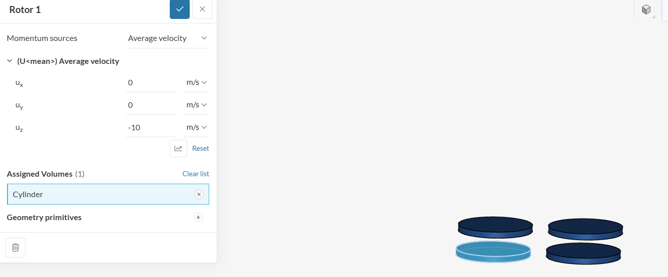
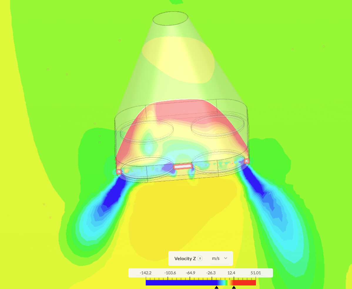
The air velocity seems to spread out immediately and unnaturally away from the rotors instead of going straight down. I have tried this with both a fan model (200 and 300Pa pressure change) and an average velocity (20m/s) model.
I am really at a loss here, if anyone has any hypotheses or can tell me if I have set up my simulation incorrectly, I would really appreciate it.
I cannot seem to make my projects public (it is an academic account) so unfortunately I cannot share the project links, but I will share as much information as I can below and I am happy to provide more if need be.
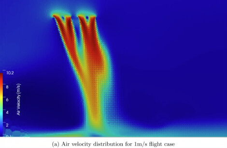
What I Expect: (from the internet)
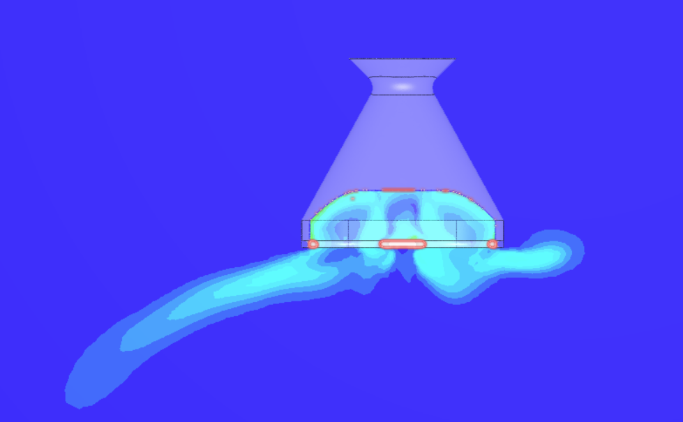
What I get: (Showing air speed velocity magnitude)
Hi @Andrewb1230
Would it be possible for you to share the project with support? and if possible also guide me to the paper. It is a little bit hard to analyze purely based on just the pictures in this case.
Thanks!
Bryan
Hello Bryan!
Yes I shared the projects with support.
I have tried a few more different things now and still it does not look right. I feel I should see a constant velocity coming out of each of the rotors, but I do not at all. I have tried adjusting the thickness of the rotor discs and changing the flow region boundary conditions around, to no avail.
Please let me know what you think.
Andrew
Hello @BryanArsenio!
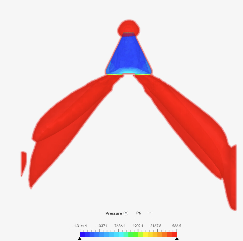
I just wanted to say the project is shared with support and I am still encountering this problem. I really am stuck here. If you have any idea how I can fix this I would really appreciate the help. As you can see below in the last run, the air seems to come out towards the sides of the rotors instead of evenly across them.
Hi @Andrewb1230,
Sorry for not keeping an eye on this thread, but would it be possible for you let me know which paper or reference do you use as the benchmark, as I couldn’t find any faults in your simulation besides the fact that the reference solution you showed contains propellers which might affect the strength of the downwash.
Also, if the problem is already fixed, it would be great if you can share on how did you fixed the problem.
Thanks!
Bryan
Hello @BryanArsenio ,
No, I could not find a fix for this issue. I have basically given up on using CFD because I could not find a way to make it work despite the simulation being very simple.
I do not have a benchmark. The reference image I show above is one I pulled from google images. If you type “Quadcopter CFD” you will find many images that look like this one. I was simply using it as an example of what I expect my simulation to look like. The actual scientific interest I have in this simulation is the suction force created above the inlet hole. The downwash being correct is essentially my control – how I know that my sim is working properly.
As you can see in my images and my project, the air seems to only flow out of the side of the rotor at an angle for an unknown reason.
I would be grateful if we could schedule a video call so we can both understand what is happening as I followed the simscale tutorials to the T, and tried all the ways I could think of to move air through the holes - rotating bodies, average velocity, and fan model – nothing works.
Please let me know if this would be possible as it would of great help for my thesis, otherwise I will have to throw away this work.
Thank you very much,
Andrew
Hi Andrew,
I will have to take a look at the problem deeper, once I have an explanation and a modeling approach in mind I will let you know. If by Tuesday I still have not send any message here, feel free to ping me here, or by sending an email to barsenio@simscale.com.
Thanks!
Bryan
Perfect!
Thank you so much Bryan! I will