Let me know if this helps and feel free to add more questions to this thread as you have them. I’m sure other members will be happy to jump in as well.
Hello,
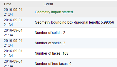
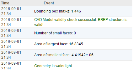
I received additional shell elements when I import the solid model. Should I
remove them and how to find them? In the CAD program the 3D model is OK.
Adding more levels of refinement to the MRF surface (4 or 5) should improve the mesh in this case. I’ll see if my colleague @AsadAli can have a look, he has more experience in this area.
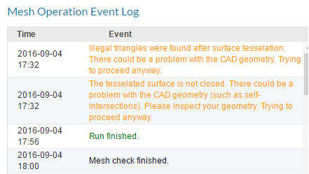
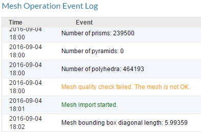
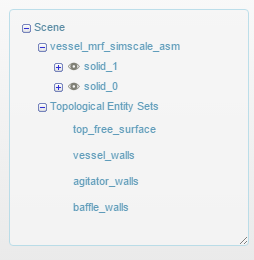
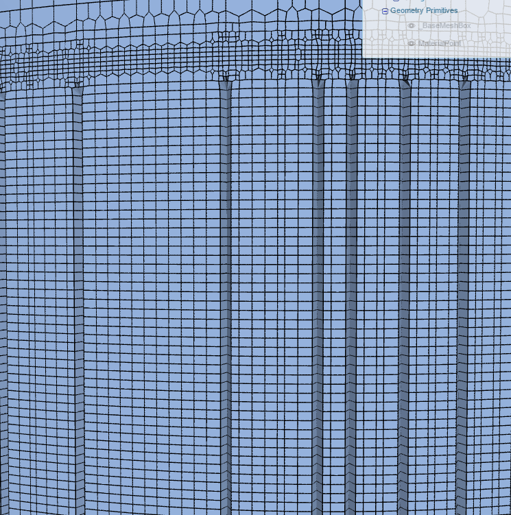
Since the distance between the rotor blade and vessel wall is very small, we have to extra refine this region. Your mesh is deformed because of insufficient mesh refinements. Mesh refinements can be tricky to use especially setting the right refinement level. We made a mesh using your geometry which you can import from here.
To get the workable mesh, keeping the overall mesh size small, we further refined critical regions. I would suggest to simulate with this mesh, hopefully simulation will converge but if it doesn’t then we will have to further refine the mesh. If you have any question, feel free to contact. Cheers
Hello @AsadAli ,
First of all thank you for your help regarding the mesh refinement. I imported the project and I created simulation and ran it on Sunday evening. After about an hour the convergence plots blocked at 0.0425s. Nevertheless, I didn’t stop computing process. I tried to do this on Monday morning around 07h (Bulgarian time). Unfortunately, the system computed only until 11:50 and then I received an error message. In this way I accumulated 489 core hours.
Is it normal for the platform to compute so long?
What do I have to change in the simulation setup in order to receive results in less core hours?
Well, you are using transient flow simulation which takes lot more time than steady state flow simulation. You can run steady flow simulation for this case for fast convergence.
The computing time depends on the simulation settings, in case of transient sim. the computing times in general are very long (depending on the mesh size, end time etc). Use transient only if it is required by the problem, in most of the cases steady state sim. is fine.
Always check the solver log, if the see anything abnormal e.g high values for the fields, divergence, stop the simulation. Use maximum simulation time option to avoid burning your core hours in case of divergence.