Is there something wrong with my set up? The only values changing in the simulation are the ones in the rotating zone. I was expecting to see similar gradients of pressure and velocity changes throughout the whole pump. Another issue is that I was expecting an inlet and outlet pressure to be closer to 8.5 ft head (Currently at 1.568e+7Pa which is about 5247 ft head). Any suggestions would be appreciated
Hi there, thank you for using the forum!
Could you provide some more details regarding this project? For example, which are the runs you are referring to? Could you also include some images to showcase the issue?
Best regards,
Fillia
Hi,
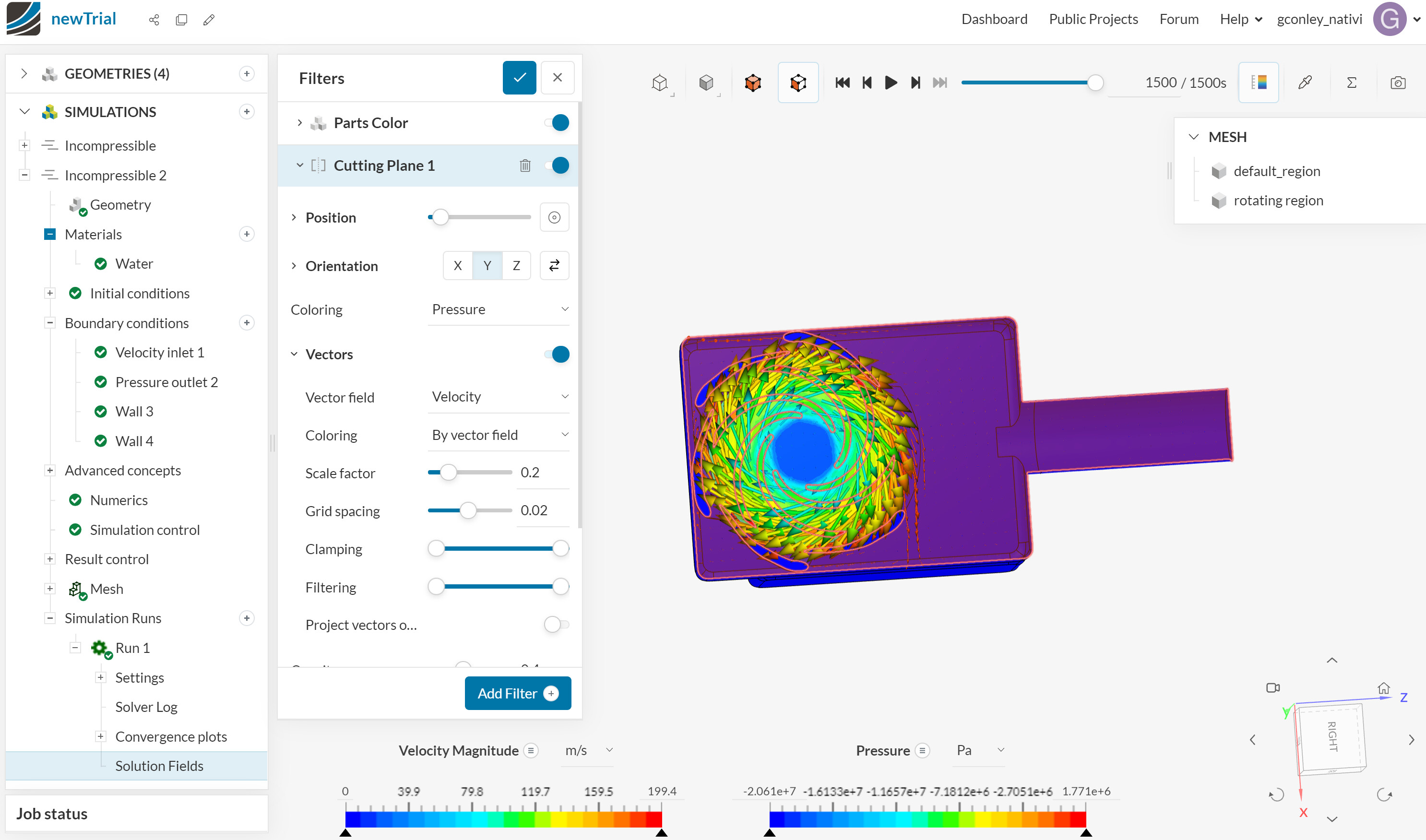
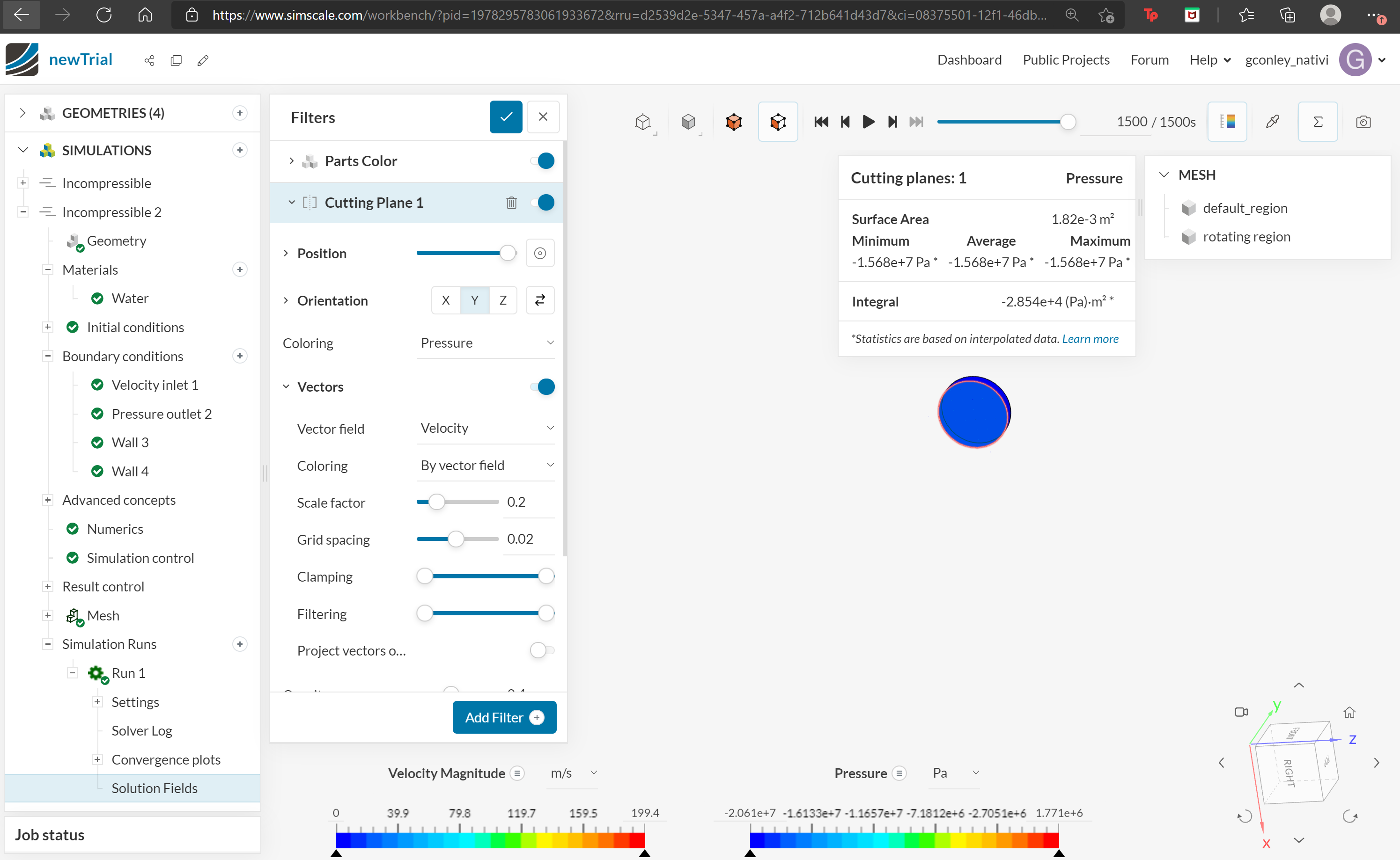
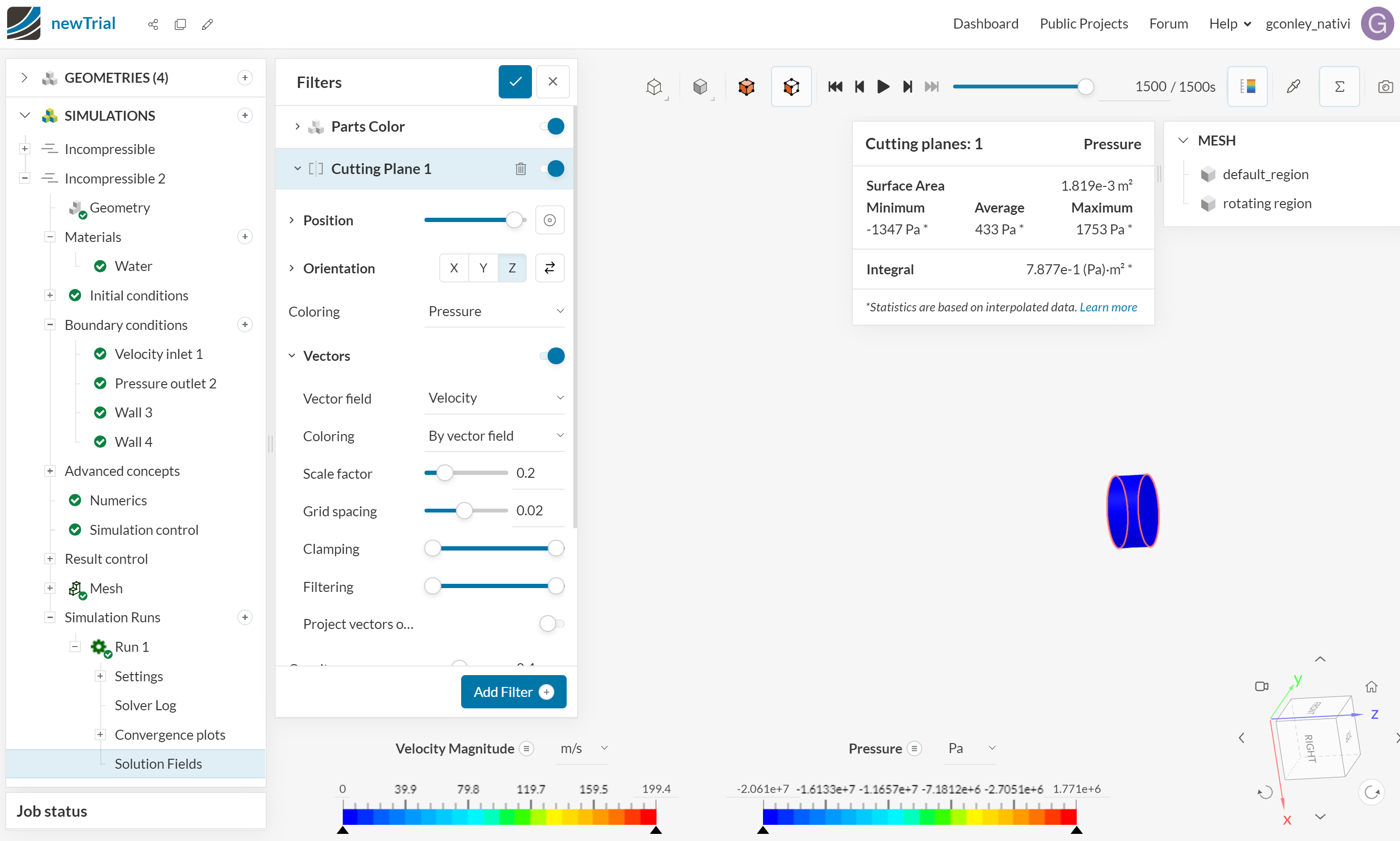
Of course! The run I am referring to is “incompressible 2”. The full project is comparing a experimental data with CFD results. The experimental data shows that for this pump the inlet and outlet head are 8.5ft with a flow rate of 58GPM. As stated above the pressures I am getting are way out of range. Attached are some pictures. The figures illustrate that the only place pressure is changing is around the impeller. I was maybe expecting a pressure gradient throughout the entirety of the model. The other two photos of snapshots the the pressures at inlet and outlet.
Let me know if there is any more details I can provide. Thank you for the help.
EDIT: I should also mention that the pump has a diffuser, that I did not include in the rotating zone. Should I include the diffuser in the Rotating zone?
1 Like
Thank you for all the details!
If the diffuser is not rotated, then it should not be inside the MRF region.
A few comments from my side:
-
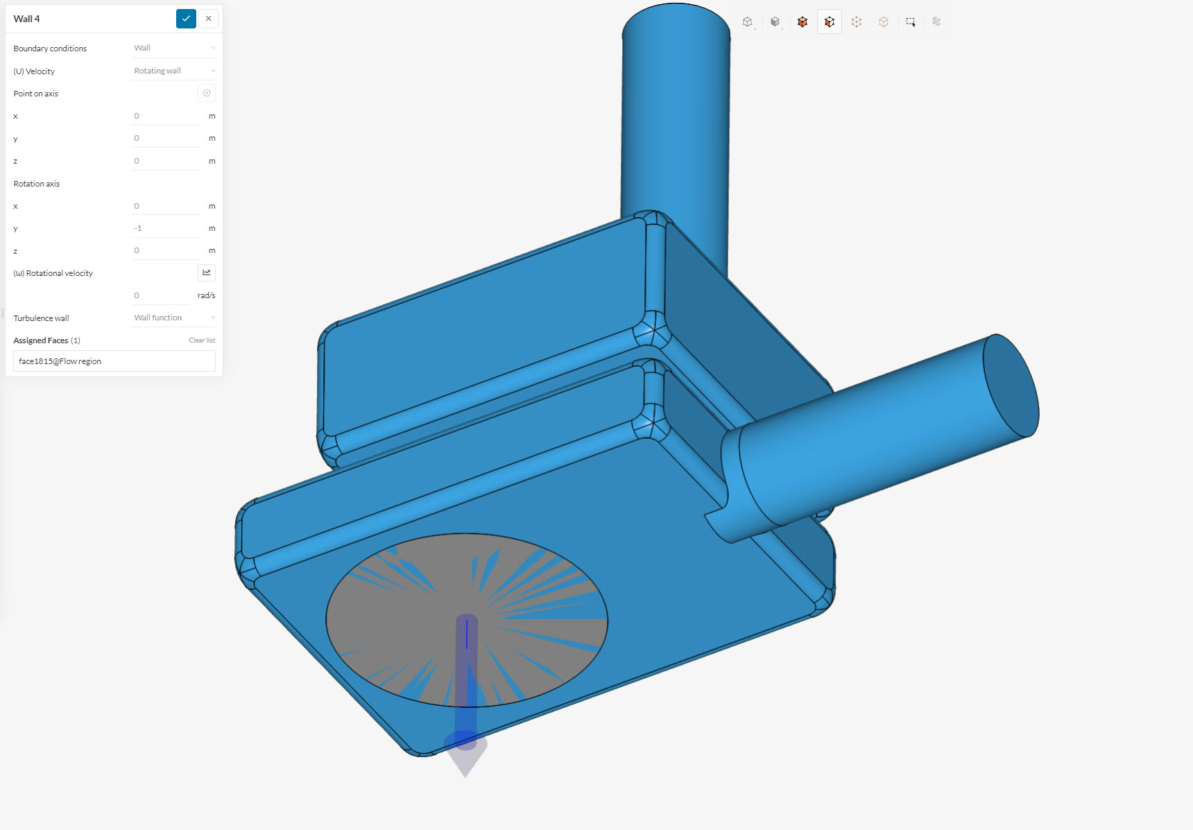
I there a reason why you included a rotating wall (with 0 rad/sec input) at the bottom of the model?
-
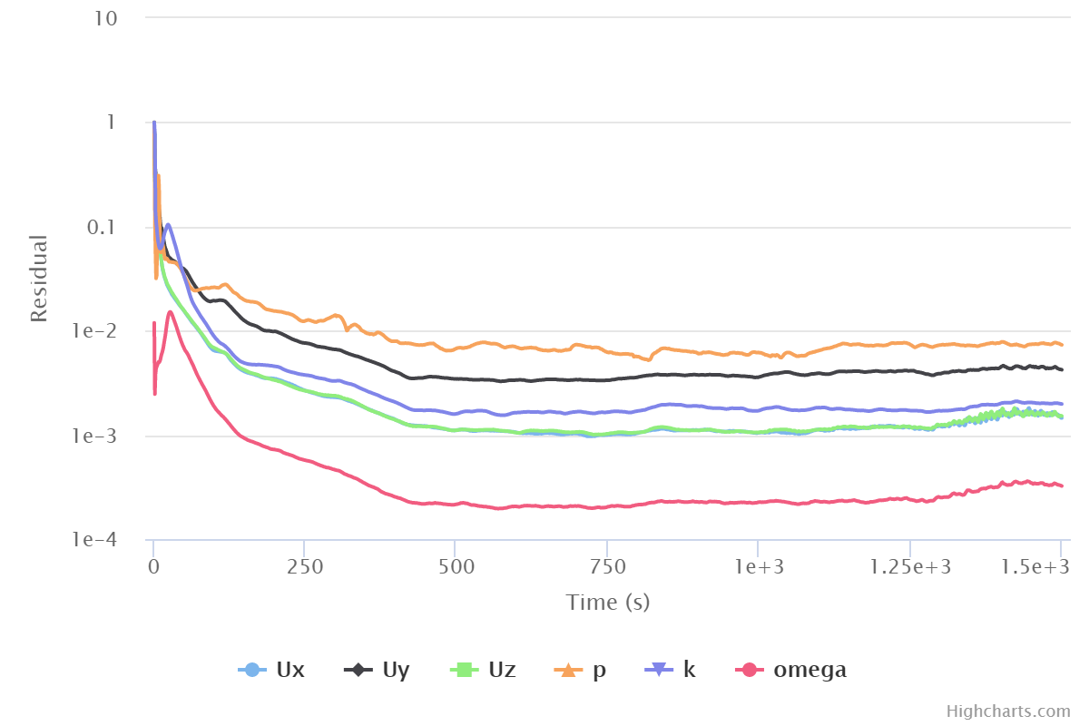
The convergence looks promising, however, I would wait for 500 more loops to check whether it is actually stabilized, or if the residuals increase a lot:
-
The rotating velocity is high and produces a stream with a max tangential velocity of 199.4 m/sec. This should count as a compressible flow then, as the Mach number > 0.3

Let me know about your thoughts.
Best regards,
Fillia
Hi Filla,
Thank you for the clarification on the diffuser! I fixed a detail on the diffuser. I found out my diffuser was backwards here is a link to the project with the diffuser turned the right way. Diffuser Correction | SimScale Workbench
The simulation I am referring to in this project is titled " Improved geometry, no rotating wall, 2000 iterations" (this is the third simulation). The run is titled “run 2”.
This new project has no rotating wall, 2000 iterations, I have better results but still not quite what I was expecting. The plots for convergence seems to be off at the outlets and inlets. Any thoughts?
-
I there a reason why you included a rotating wall (with 0 rad/sec input) at the bottom of the model?
I attached a rotating wall based on this video at 4:15: How to Simulate the Flow Through a Francis Water Turbine - YouTube
-
The convergence looks promising, however, I would wait for 500 more loops to check whether it is actually stabilized, or if the residuals increase a lot:
The link to the new simulation that I attached above has this included.
- The rotating velocity is high and produces a stream with a max tangential velocity of 199.4 m/sec. This should count as a compressible flow then, as the Mach number > 0.3
I am not sure I understand how to deal with this. Would you have any thought?
Thank you for the input!
Hi there! Give the Compressible analysis (Mach> 0.3) type a try too 
Bets regards,
Fillia
Hi Fillia,
I ran a compressible analysis and the outputs are now closer to what I expected. Thank you!
-Gabe
2 Likes