From here i am trying to understand how my results from the forces and moments calculation in the simulation software translates to finding the CoP and the forces at each contact patch. I created the vectors in solidworks to better show this graphically. Here are my results
Car simulated at
- 18.06m/s
- (0,0,0) origin (not CoG but doesn’t matter)
- 10 deg steering angle
- 0.66 deg roll
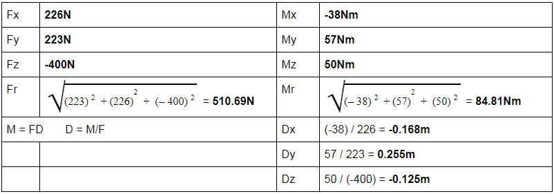
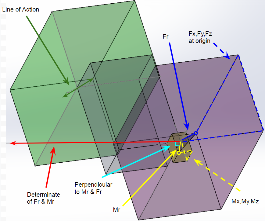
This means that the (Dx,Dy,Dz) point (-0.168,0.255,-0.125) - shown in orange, is the distance in each coordinate direction calculated from the moment equation with this point located along the line of action. Transposing the original resultant force vector - shown in blue, we can position this force vector on this new point - shown in green. This is now our “Line of Action.
The only calculation we would now have to do is to find the moment vector about this point, which should be very small and co-linear to the force vector but opposite in direction.
Now comes an area of confusion. I have also calculated the resultant moment vector - shown in yellow. When the two resultant vectors Mr and Fr are combined they form a Force-couple. When we take the determinant of these two vectors, the determinant vector is perpendicular to Mr and Fr and should intersect the line of action. The determinant vector is shown in red yet, does not intersect the LoA. I did not compute the determinant of Mr and Fr, I simply made a sketch that was perpendicular to them.
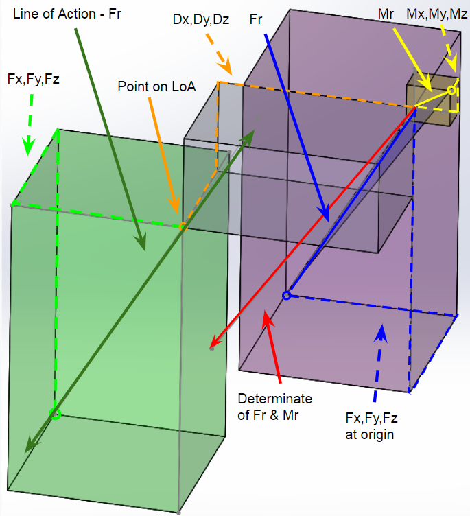
Here is another view to show this clearer. I feel like there could easily be a problem with my computations, or with the assumption that finding the distances in each coordinate direction from the moment equation gives me a point along the line of action. This could be false.