Often when doing conjugate heat transfer simulations for electronics cooling applications, it is necessary to consider the thermal conducitvity of the Printed Circuit Board (PCB). A PCB is comprised of many layers of FR4 insulator and copper. How many layers and the thickness of each layer has an effective on the overall thermal conductivity of the PCB. Because each layer is very small and detailed, it is not possible to explicitly model the PCB, and then mesh and solve the simulation. Instead, a hand caculation can be done to calculate the effective thermal conductivity for the entire board as a whole.
Looking at the image below, we can see a PCB with 1 copper layer. Note that heat transfer occurring from the top of the board to the bottom of the board is going in the “through plane direction.” This heat transfer has to go through the various FR4 layers and 1 copper layer in series. The total effective thermal conductivity can be calculated as a set of (thermal or electrical) resistors series.
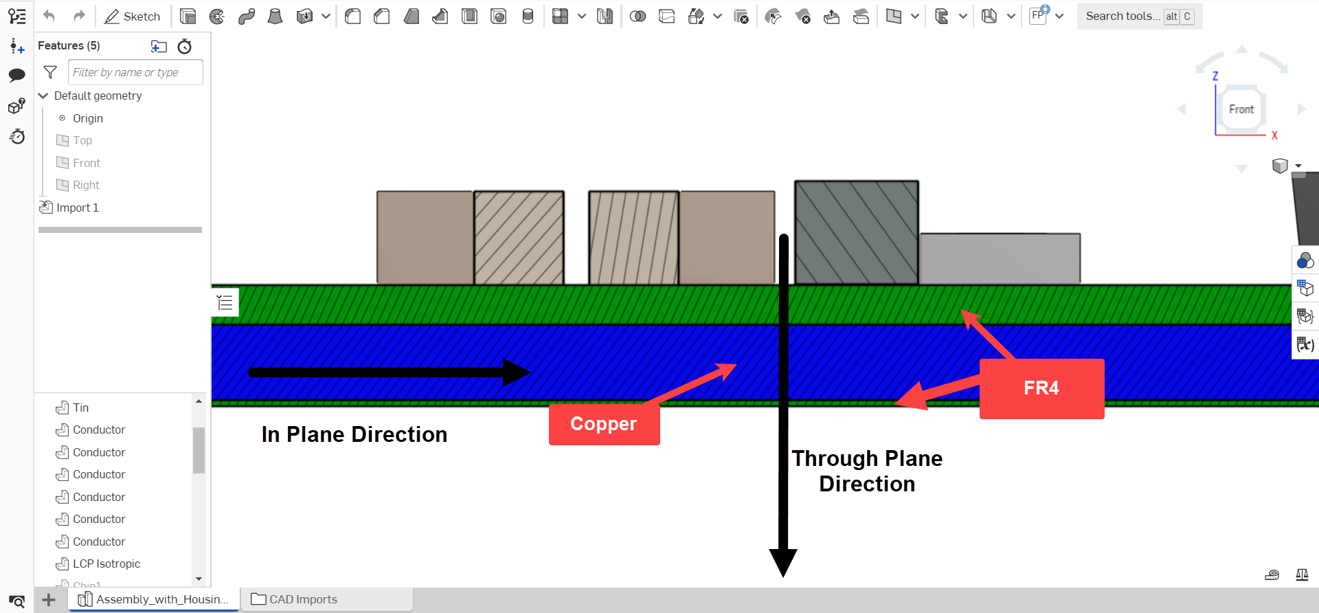
On the contrary, heat transfer occurring from the left side of the board to the right side, or in plane, is more similar to a set of resistors in parallel. Most of the heat will move to the copper layer and then move down the board via the copper trace. The total effective thermal conductivity can be calculated as a set of resistors in parallel.
For further information, I recommend checking out a few of the resources below:
16.4 Thermal Resistance Circuits (MIT notes)
Heat Transfer - Chapter 3 - Thermal Resistances in Parallel, Contact Resistance, R-Value (Youtube lecture)
Lastly, while doing the hand calculations on paper is quite easy, I’ve put together this Google spreadsheet which automatically calculates the effective thermal conductivity of your board based on layers, thickness, and properties. Feel free to make a copy and use it yourself.
Best regards,
Matt Bemis