Hey @rarrese, yes I’ve seen your meshes and that’s why I mentioned them in my previous post.
For me so far the best approach to mesh geometry for CFD cases is snappyHexMesh which means manual settings of the most important parameters. In fact you don’t have to change a lot and all I do is:
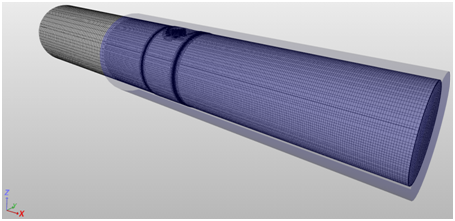
BOUNDARY LAYER
- I set _BaseMeshBox parameters – obvious

- I change Feature Angle and slip Feature Angle from 60 to 350 – as far
as I understand it it’s an opening angle of two surfaces sharing a
common edge.
(to avoid misunderstandings)
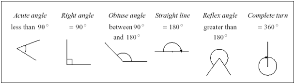
source: http://www.cimt.plymouth.ac.uk/projects/mepres/book8/bk8i11/s1eg1angles.gif
I know @dheiny wrote in one of my topics that it’s far enough to increase Feature Angle up to 180 degrees, but as far as I’ve noticed it may not be. Further, David suggests we should change only the first value, but when I leave slip Feature Angle at 60 there is no response from the mesher and BL cells are still inappropriate. Anyway at the moment setting both features at the same value works the best for me.
Two strange behaviours of BL you see are: stair stepping (disappearing cells) and layer compression (cells’ squeezing). These features are to help mesher cope with difficult regions, where extruding even a single cell of BL is problematic. Additionally, in relative meshing, compression is / may be a result of base element size. I’m afraid we have to accept BL’s lack of continuity in some areas. Just try to check your mesh carefully.
Topic about relative meshing:
- I also increase nSmoothSurfaceNormals from 1 to 3
REFINEMENTS
I did only one region refinement here. The valve area and the wake behind it – you forgot the wake is what causes the convergence problem in this case.
Further two surface refinements for valve surface and this step in pipe’s wall:
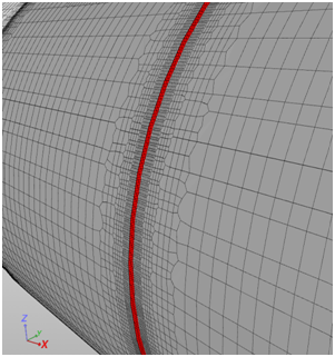
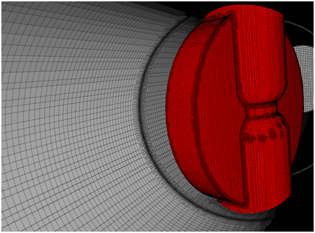
And don’t ask me why there are these patches of additionally refined mesh on valve’s surface. I guess there must be something slightly different with geometry surface there and hence this unexpected behaviour.
I avoid using Feature Refinement (edge refinement) as it often causes me troubles. I think a bit more effort with manual surface refinement is better approach and gives me greater control over the mesh.
INVALID CELLS DETECTION
I’m afraid at this stage there is no such possibility. But you are absolutely right and it would make our life easier if there was a tool which could highlight invalid elements. @dheiny what do you think? Is it feasible in the near future?
TIME STEPS
Well, I’m a bit confused here – the labelling is clear to me. In other programs, regardless of steady or transient state, you still set the time step and it does have an influence on simulation run…
SIMULATION
I’ve tried the valve already and after a few attempts I went back and started with more simple case – to reduce the number of elements and time needed for experiments. So far I was able to achieve expected convergence in a steady state for both k-e and k-w models. (I just don’t control it fully ![]() ) And it seems to me that we have to switch to epsilon (which I don’t like) as I’m unable to reach minimum Y+ values for omega. – Everything points at very dens mesh here. In such situation we won’t be able to provide required first cell height.
) And it seems to me that we have to switch to epsilon (which I don’t like) as I’m unable to reach minimum Y+ values for omega. – Everything points at very dens mesh here. In such situation we won’t be able to provide required first cell height.
Ok, that’s it for now. I continue my experiments and I’ll let you know the results and conclusions.