Hi @rarrese,
great to see you digging deeper into that project! So regarding the BC setup:
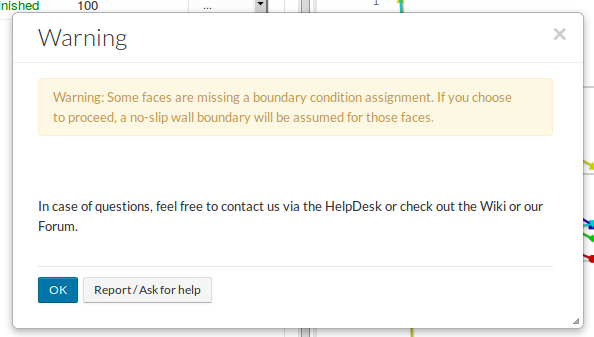
- Missing Wall BC: For every boundary of the flow domain, where no Boundary condition has been assigned, SimScale automatically assigns a no-slip wall boundary. You can see this once you create the run, the message below is shown. So the no slip wall BC is used, but you don’t see it explicitly. But now that you are raising this, I think especially for library projects it would make sense to have all boundary conditions explicitly created to make them really visible to avoid confusion. I’ll keep this in mind when creating the next simulations.
- Inlet BC: The setup I used is a velocity inlet BC, where turbulent quantities are set as fixed values derived from the initial condition values (velocity inlet documentation). You’re right - if you would like to set the turbulent values explicitly, you could choose a custom BC applying fixed value for velocity, zero Gradient for pressure and fixed values for the turbulent quantities, exactly how you did in your sim
- Outlet BC: I could have chosen the pressure outlet, which would be the most simple one (zero gradient for velocity and turbulent quantities as well as a fixed value for the pressure, see pressure outlet documentation). However as the flow domain downstream of the valve is quite short (actually I would say it’s too short) I suspected potential backflows, I decided to go with an inlet-outlet BC for the turbulent quantities. They basically switch between a zero gradient and a fixed value BC depending on the velocity direction. This means if a partial backflow appears at the outlet, for these cells a fixed value for the turbulent quantities is applied (this is why there are turbulent values given) which makes the simulation more stable.
I briefly checked on your simulation setup and in general it looks good to me - the BC setup makes sense! A couple of points, that might be the reason for the convergence behavior you’re seeing:
- Transient effects: During the project setup I also ran a quick transient analysis of it and behind the valve, there appears a flow separation that creates a transient flow pattern, that can not be covered correctly by a steady-state solver, which could lead to the residuals not going down. This gif shows a bit what I mean:
- Turbulent initialization: You’re using different values for k and epsilon in your inlet BC than your initial conditions. Is this on purpose? However I think that should probably not be the reason as this might only lead to a slower convergence but not to the oscillating behavior you’re seeing.
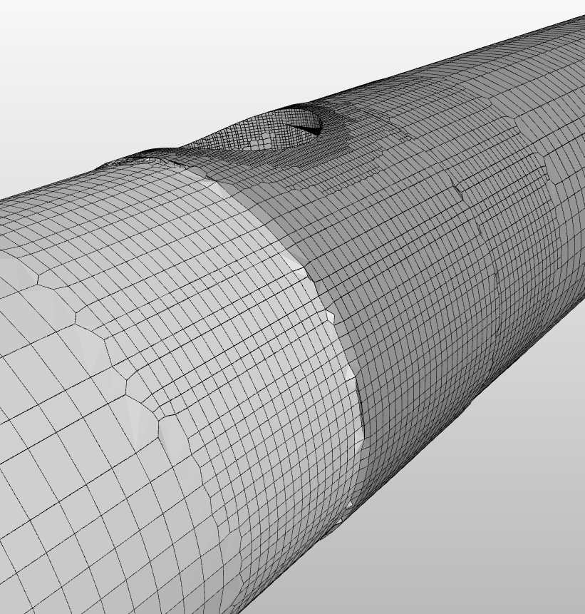
- Mesh: Especially the edge before and after the valve are sensible to the layer inflation. It seems not to be well meshed in that area. How about increasing the refinement level of your region refinement a bit more there? (The one with the sphere)
- Flow domain: The flow domain is too short as the downstream flow interacts too much with the outlet patch. I used this project in a webinar a couple of weeks ago (video is here) where I extruded the flow domain more.
@gholami, @jprobst, @anon5767293 - did I forget/overlooked something? Maybe you have another hint?
Hope that helps!
David