Project link: https://www.simscale.com/workbench/?pid=743018340437027273&mi=spec:787efe84-cf1f-4517-8361-511469e5ef0d%2Cservice:MESHING%2Cstrategy:23&sh=16
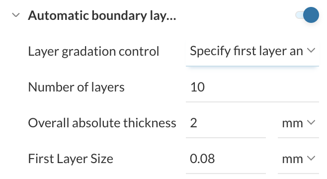
I’m working on senior capstone project on vertical axis wind turbines. We’re are using steady state MRF study with a k-omega SST turbulence model. We have determined that we need to directly resolve the boundary layer with y+ ≤ 1 in order to get accurate results for the power output of our turbine. Right now, we are using an automatic boundary layer the following specifications:
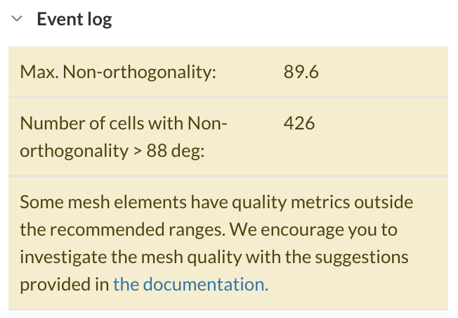
With these settings we are getting the following warnings about mesh quality.
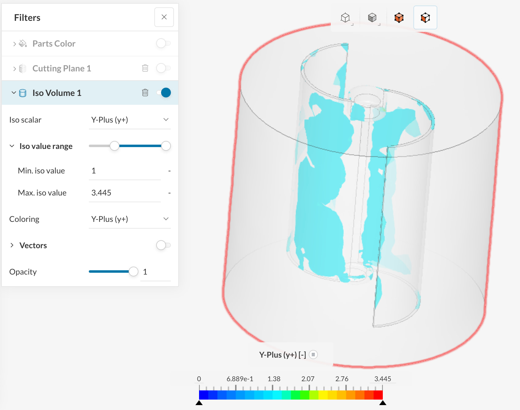
In addition, we are not sure whether our meshing is appropriately capturing the boundary layer. We’ve tried plotting the y+ values using an iso-volume, but we’re having difficulty interpreting the results. Does anyone have advice for how to use the iso-volume to figure out if we’re achieving y+ ≤ 1 or for how to improve the quality of our mesh?
Hi @ElliotBurroughs,
Indeed there seem to be some problematic elements in your mesh - I’d recommend using the mesh quality view to locate where those bad cells are forming. If they sit around sharp edges, tight gaps, or layer collapse zones, reduce the inflation aggressiveness first - typically fewer layers, a slightly larger first layer, or lower total thickness gives a cleaner mesh than forcing a very thin stack.
For the y+ check, the best reference is SimScale’s guide on controlling and analyzing y+. If your iso-volume is filtered to y+ > 1, then any visible regions mean you are not fully wall-resolved there. What matters is the blade wall distribution, not the bulk volume.
So, I would prioritize mesh quality over pushing y+ lower everywhere.
Cheers,
Igor