Hello everyone! I’m doing a half car simulation for my school’s FSAE team but am seeing some strange results regarding the boundary layer refinement. Last year’s simulations ran with the same surface refinements that we’re using this year, with five layers on “Inflate boundary layer”. This year, we ran a simulation without our undertray with five layers as well and got reasonable results in post processing. We added our undertray to the model and have had to turn down the inflate boundary layer to three levels to get the model to mesh without crashing. Firstly, does it seem reasonable that the cell count was increased so drastically by adding our undertray that we have to turn down that boundary layer by 2 levels? We’ve had to upload the file as an STP since STL files give us errors with our cell zones. Secondly, the post processing looks completely different with different steam line trajectories, pressure distribution, etc… all having just changed that boundary layer. Any thoughts on why our results have changed this drastically?
I will tag the @cfd_squad here in any case. Also I am not sure about your streamline settings if they have the exact same starting point, properties etc. so I would rather look at the drag and lift if they make sense. Have you checked your y+ in the PP results? Maybe @fsite, @yosukegb4 or @DaleKramer can comment on your setup.
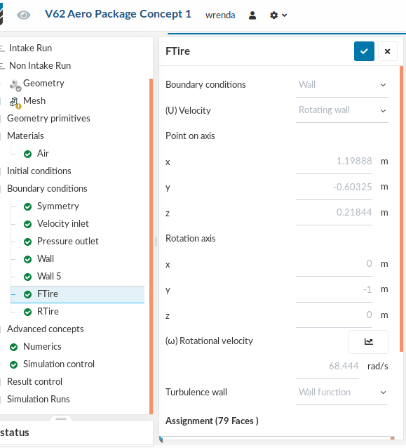
In the simulation with the reduced inflate boundary layers, the lift/drag values were drastically different on every probe. Wheels, body, FWing, RWing, etc. Nothing was consistent between the results. Yet the only thing that changed between the two simulations was that boundary layer reduction. We’re also not sure about the rotation of the wheels in our setup. According to the right hand rule, with the y-axis point to the center of the car, the rotation axis should be -1 in the y, but in our post results, the tire squish seems to be behind the tire not in front.
Hello wrenda! Could you send the link to the 5 layered project as well?
Edit: I am pretty positive the rotation axis is the problem, try changing the y to 1 if you want to keep a negative angular velocity, or the other way around That must explain the big results difference.
The axis is the same, but the angular velocity is 68.444 instead of -68.444 in the first concept, so I suggest you change the settings of the new design case give it a try and share the results with us so we could take a look at the boundary layer addition as well. My guess is that it won’t have much impact, but we will see!
We’ve set up a new simulation with the angular velocity set to 68.444 instead of -68.444, and are monitoring the force outputs. So far, they are following the same trend in forces as the simulations that we have run on this concept before with reversed angular velocities. I checked to see if our MRF assignments for the wheel centers were correct, and they have the same settings for rotation as the wheels themselves.
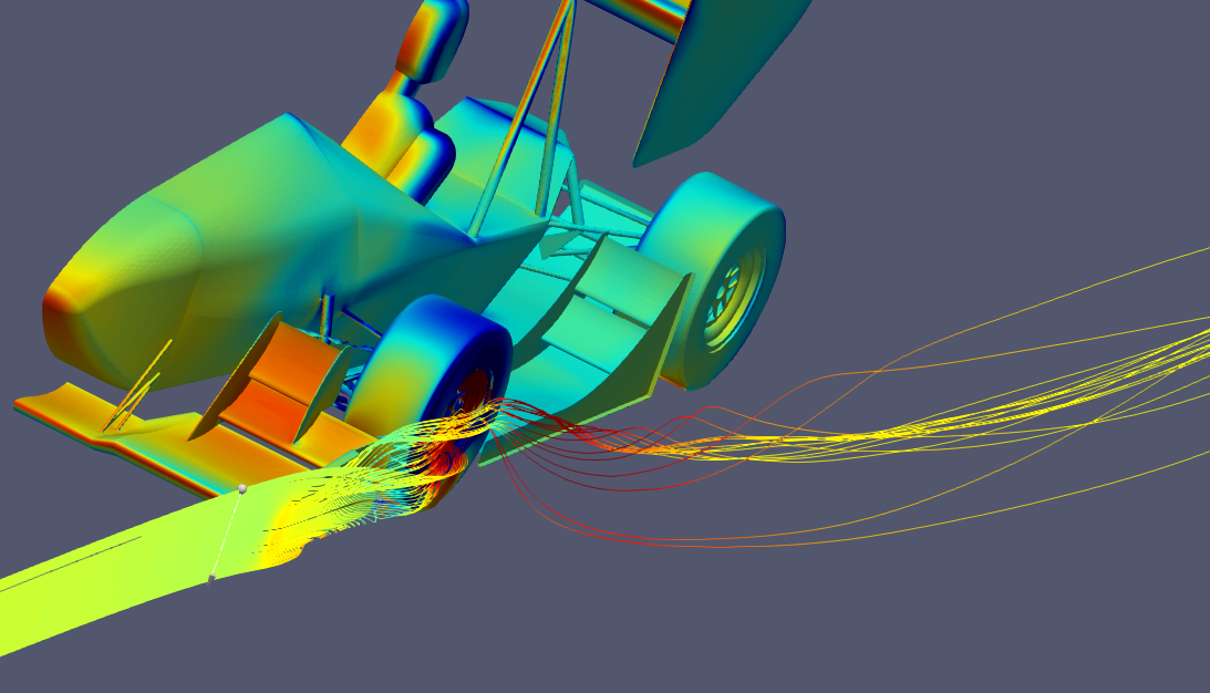
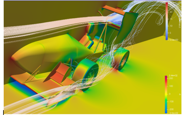
We’re working on getting some post processing results to show to see if anyone else thinks the flow and pressure distribution makes sense. Thanks for all the help so far!
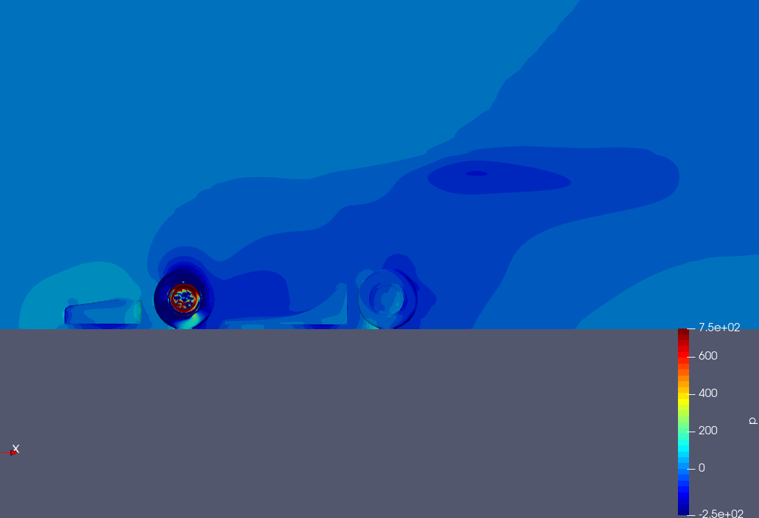
Hi all, we’ve found the issue that was causing the strange flow behavior and force results! An MRF zone was applied twice to the wheel center, which resulted in a crazy pressure increase at the front tire which messed up the flow around the rest of the car.
Our flow results look much more sensible now, and we have the tires spinning correctly now. The forces do seem a bit low compared to what I would expect using my intuition from last year’s simulations, but I think the settings for turbulent kinetic energy and specific dissipation rate may be to blame. More results to come…
 Can you make sure that the project is set to public so that we can have a look at that?
 That must explain the big results difference.